This thread has been locked.

If you have a related question, please click the "Ask a related question" button in the top right corner. The newly created question will be automatically linked to this question.

TLV9061: Damage issue

Part Number: TLV9061
Other Parts Discussed in Thread: LMV721, LPV821

Hi Team,

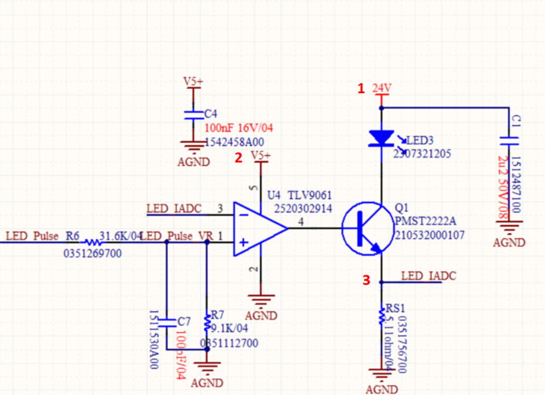
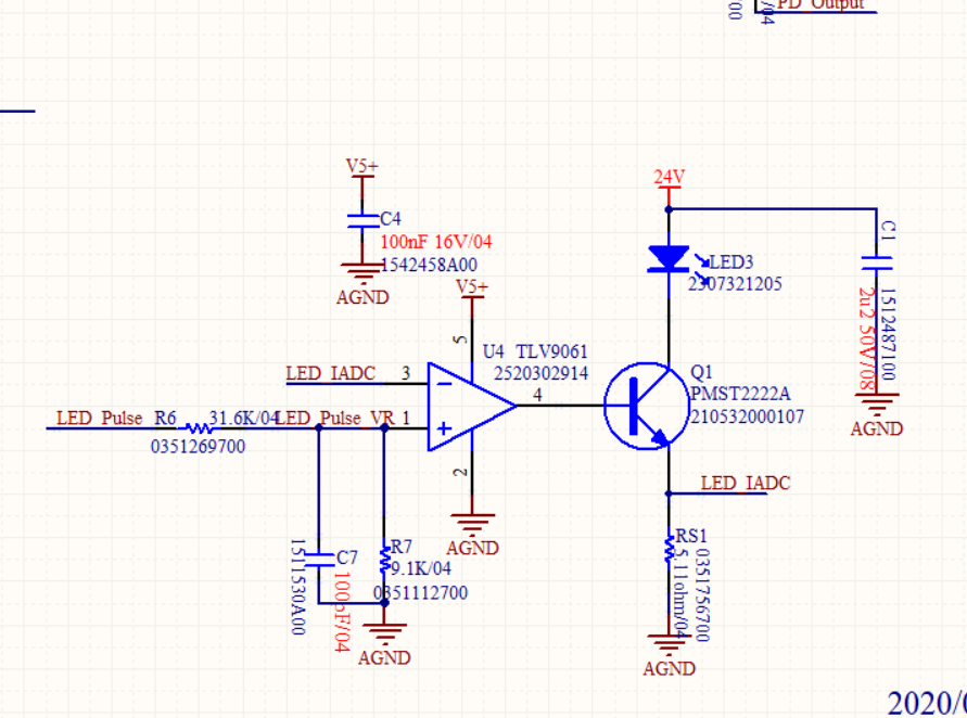
My customer used LM721 to implement below circuit for years without damage issue. Then, he changed to use TLV9061 for better cost advantage. Recently, he got 3 FA return units from his customer and TI help FA analysis that shows pin 3 got damaged and short to GND. This issue also be found at customer's factory at last manufacture, fail rate is 1/500.

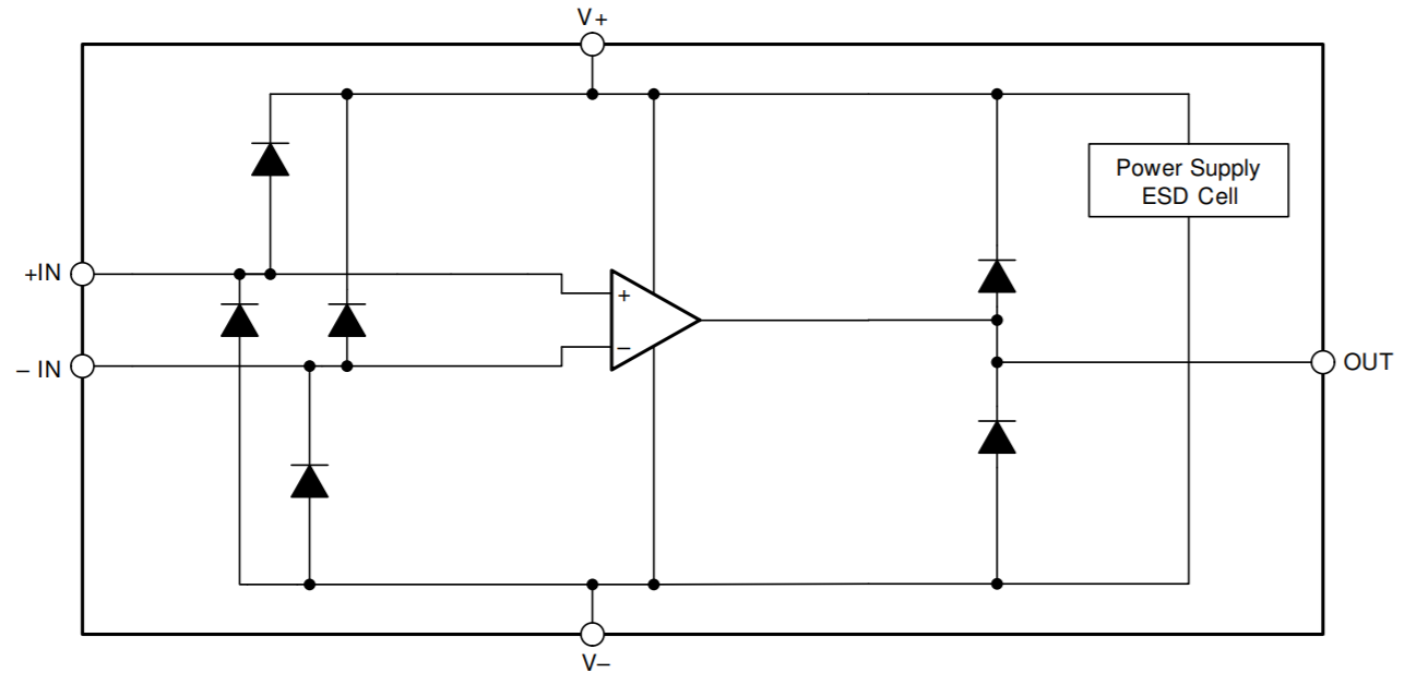
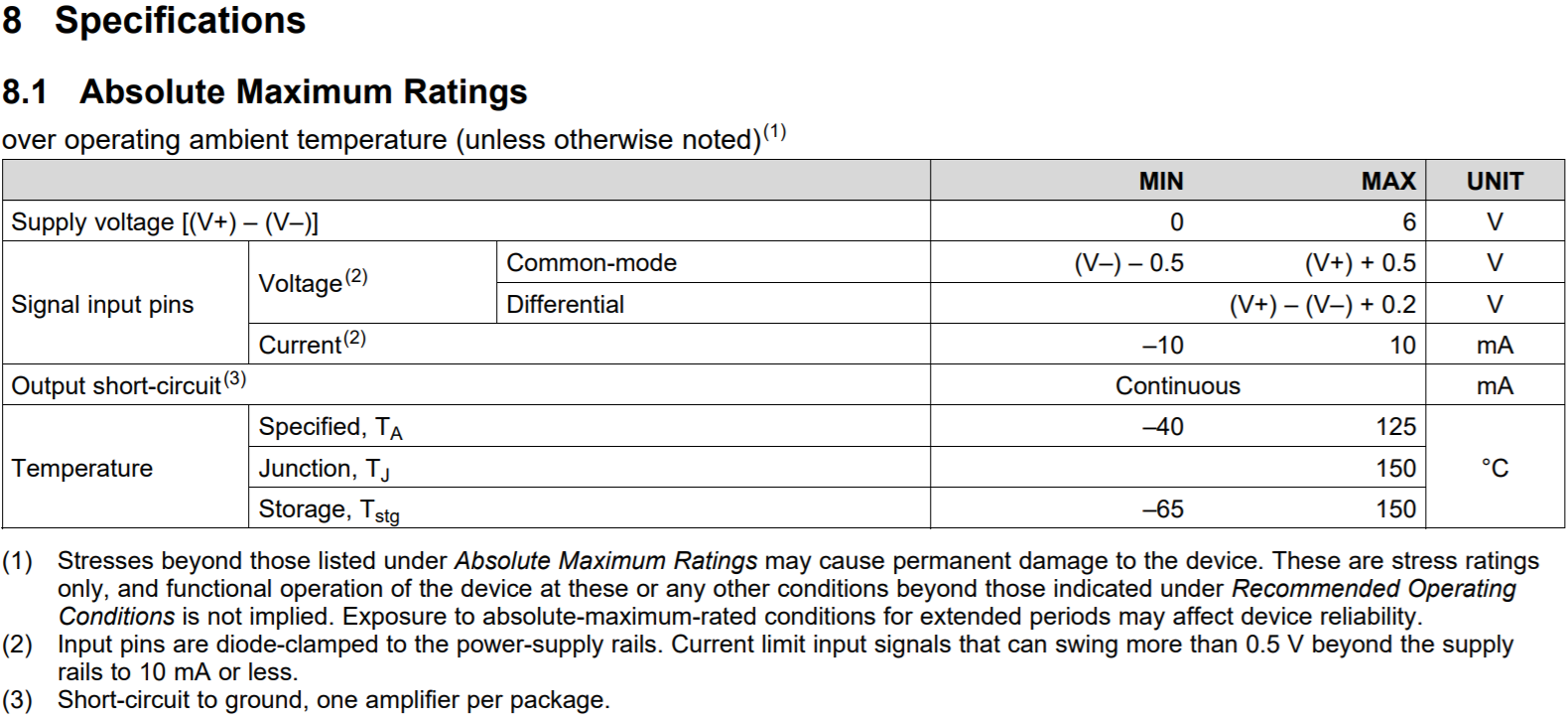
Please comment is there any potential risk to use TLV9061 in below circuit and why LM721 doesn't have? What is the difference between these two parts?

Besides, any recommended parts that is P2P to TLV9061 for this application? The criteria is GBW>5MHz, slew rate > 2V/us.

LED_Pulse from MCU, 5V level, PWM frequency is 10KHz, on duty is 2uS.

Thanks a lot.

Vincent Chen

  • Former Member
    0 Former Member

    Hi Vincent,

    I think this is most likely an applications issue caused by an overvoltage on the inverting input (pin 3).  The vast majority of our devices have ESD diodes on the input pins to protect them from ESD strikes.  The structure looks as shown below.

    You can see that, when the input voltage exceeds the V+ voltage there is a chance that the protection diodes will turn on.  These components are meant to protect from very brief ESD events, but not continuous operation from an overvoltage scenario.  The data sheet of the device has a section explaining this in the absolute maximum section and also note 2 below.

    If the diodes turn on for a significant period of time, they can burn and be destroyed.  This will damage the input of the device.  I think this is what is happening here because the supply voltage to your amplifier is 5V (2), but the output leg has a reference voltage of 24V (1).  Thus, I think the output of the NPN (3) is likely outputting a voltage that is greater than the 5V supply of the amplifier.  This will cause the ESD diodes to turn on.

    What we typically recommend for these scenarios is to place an input resistor before the op amp input to protect against current levels above 10mA, and preferably 1mA.  Even better would be to have the voltage at node (3) decreased below 5V so you do not violate the abs max specification.  You can learn more about this topic by checking out the TI Precision Labs presentations on the subject.

    Lastly, the reason why you only see some of the parts fail is that operation above the abs max specification can cause damage at different points and it is not easy to predict exactly when the damage will occur.  It can vary from device to device.

    Regards,
    Daniel

  • Hi Daniel,

    Thanks very much for the advice. My customer still would like to know what's different between LMV721 and TLV9061, since he uses LMV721 for 2~4 years without having such kind damage issue. 

    Customer agrees to add a series resistor at next project but his current project is almost MPed and cannot modify PCB. He would like to try LMV821 that is P2P to TLV9061, he thinks LMV821 maybe as robust as LMV721. That is why customer asks this question and wants to have more confidence to switch to LMV821.

    Thanks a lot.

    Vincent Chen 

  • Former Member
    0 Former Member in reply to Vincent Chen64988

    Hi Vincent,

    To answer your question, I took a closer look at your original problem statement.  Frankly, I do not think my initial analysis was correct.  Because RS1 is so small, the voltage that will form across the resistor is likely to be small even for larger currents.  This type of fault would be too small to turn on the ESD diode and would also suggest a pin3 short to V+ through the ESD diode, rather than a pin3 short to GND.

    I spoke about your customer's issue with a colleague of mine who has actually seen a very similar issue before.  The problem, in that case, was caused by poor layout of the ground node.  This ultimately led to an uneven ground voltage, which caused the voltage on IN+ to drop below the ESD diode limit.  The ESD diode was turned on and the input was damaged.

    I think something similar may be happening here given the symptoms and the PWM input.  Would the customer be willing to share their PCB via private communication?  The series resistor will offer extra protection, but it would be nice if we can find the root cause.

    As for your question of the differences between the LMV721 and TLV9061, it is difficult to tell with real certainty what may cause one device to be damaged before the other.  The reason why is because, as far as I can tell, the ESD protection structure used on these devices is the same style.

    I will say that there is one noticeable difference in the data sheet.  The common mode voltage in the electrical characteristics table of the LMV721 goes down to -300mV, whereas this value is only -100mV for the TLV9061.  It is possible that the voltage on pin3 is somewhere in this region and could be causing the issue, but it is not for sure.  It may be helpful to have the customer monitor the voltage on pin3 versus GND on the V- pin of the amplifier, not GND somewhere else in the circuit.  In other words, the oscilloscope probe can go on pin 3 with the scope's GND connection on pin 2.

    As for the LPV821, I think its performance is more likely to be like that of the TLV9061 for two reasons.  First, it is a newer part and I do not think it is related to the LPV721.  Second, the suggested common mode region of this device goes down only to V-.  This is more strict than both of the other devices.

    Hopefully, this is more helpful.  Please let me know if I can offer anything else.

    Regards,
    Daniel

  • Hi Daniel,

    Thanks for your advice. I have discussed with my customer and he doesn't have good PCB board on hand to check the waveforms since all boards are in factory. He can provides us the SCH and layout file for reviewing, I will send them to you by mail.

    Thanks very much for your support.

    Vincent Chen

  • Former Member
    0 Former Member in reply to Vincent Chen64988

    Hi Vincent,

    I have taken a look at the layouts and sent you an email.  I do not believe I have found the root cause yet, but hope to have provided some useful advice to the customer.

    For now, I am going to close this thread so we can continue to work on this via email.  If you need to do so, please feel free to re-open this thread when necessary.

    Regards,
    Daniel Miller