This thread has been locked.

If you have a related question, please click the "Ask a related question" button in the top right corner. The newly created question will be automatically linked to this question.

2 OP-Amp buffer for high-impedance sensor capable of +-1V

Other Parts Discussed in Thread: TLV9002, LM358LV, LMC6035, ADS112C04

Hi,

I am doing measurements with my own electrochemical pH sensor and need a buffer for two electrodes, one reference and one working electrode. The higher impedance the better essentially. At my disposal as supplies I have +3.3V and ±2.5V.

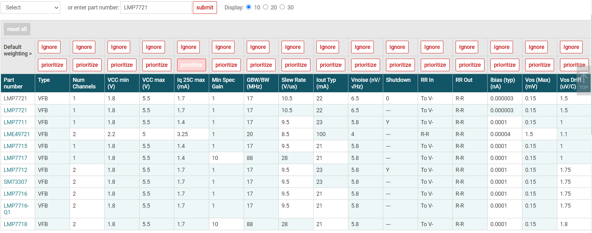
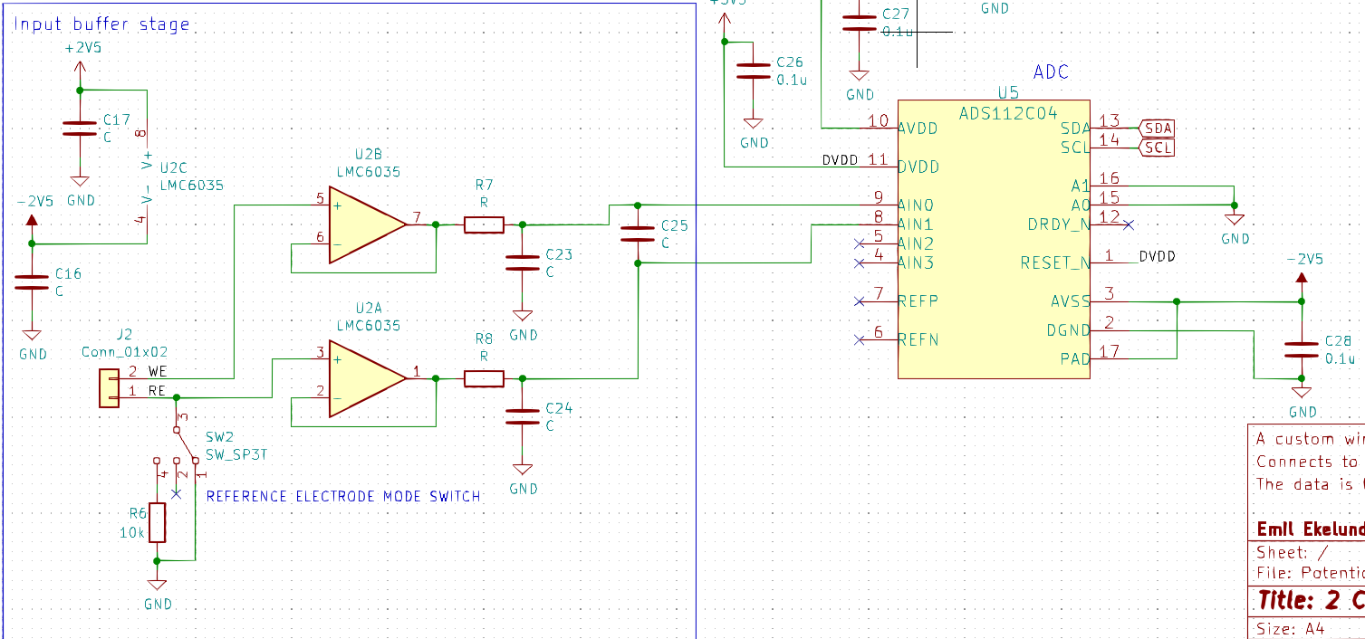
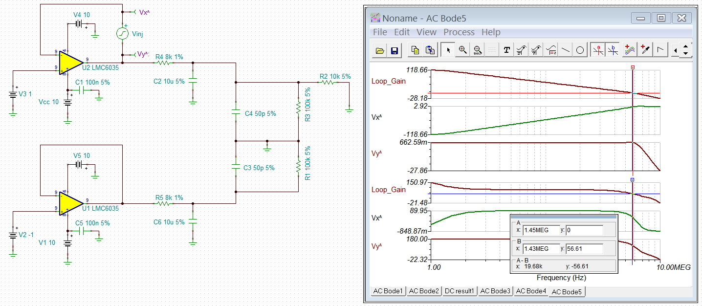
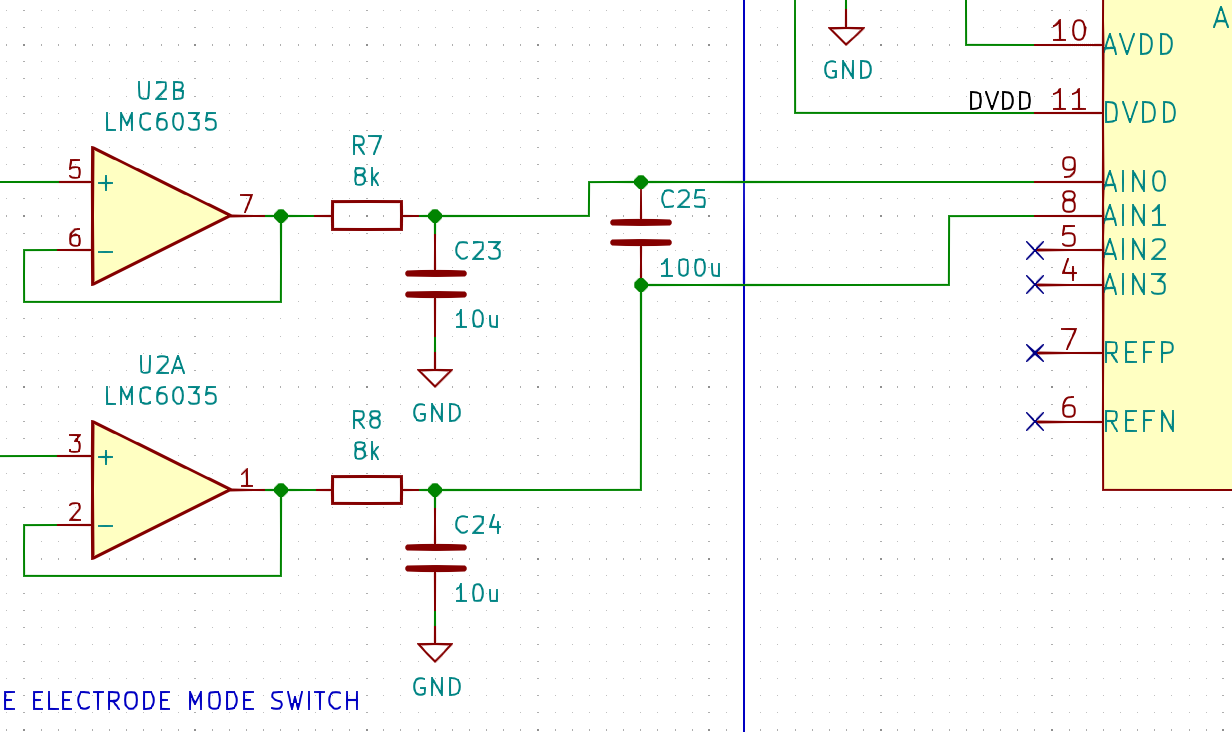
The circuit setup is as following. Is there any such amplifier in a small form factor suitable for my purposes?

Best regards,

Emil

  • CMOS opamps have high impedance inputs. For example, the LM358LV has an input bias current of 15 pA, the TLV9002, 5 pA.

    You can use other parameters (offset voltage, GBW) for choosing the buffer.

  • Thanks for the reply.

    I actually think that the bias voltage needs to be even lower due to the sensitivity of the circuit.

  • What is the limit on the bias current? (And what offset voltage, GBW etc. do you need?)

    The unity-gain stable opamp with the smallest bias current is the LMC6035, according to the search function.

  • Hi Emil,

    Thanks Clemens for the technical support. 

    TI has multiple precision op amps to select from per the application. Enclosed is a pH design application note (SNOA529A) for your reference. 

    https://www.ti.com/lit/an/snoa529a/snoa529a.pdf?ts=1601652376031&ref_url=https%253A%252F%252Fwww.ti.com%252Fsitesearch%252Fdocs%252Funiversalsearch.tsp%253FsearchTerm%253Dph%2Belectrode%2Bapplication%2Bnote

    You may use the following tool to find an equivalent op amp for your application. You may also search for equivalent LMC6035. as Clemens suggested as well. 

    https://www.ti.com/amplifier-circuit/op-amps/cross-reference.html?keyMatch=OP%20AMP%20CROSS%20REFERENCE%20TOOLS&tisearch=Search-EN-everything

    If you have any questions, please let us know. 

    Best,

    Raymond

  • Hi and thank you for the reply,

    Regarding the paper "Designing with pH electrodes" I have used that with success before. However, for my new design, I do not want to use a V-offset. I want to ground or leave the reference electrode floating. Therefore I need an OP-amp capable of directly handling ±1V on its inputs. The LMC6035 seems to be what I am looking for. I will take a closer look and come back here if I have any questions.

    Best regards,

    Emil

  • Hi Raymond,

    I have now updated my design with the LMC6035. I have two remaining questions.

    1) I could not find anything about bypass capacitors in the datasheet, are they needed and if yes, what size?

    2) I need help with the RC low-pass filter design. Are there any restraints as regards to capacitive load? Ideally, the low-pass filter would go as low as 2-5Hz. However, this might not be possible if the capacitors are too big. Additionally, the differential capacitor that is on the input of the ADC is supposed to be about 10x the size of the common mode capacitors in the RC-design. Do you have any suggestions?

    The reference electrode is connected to a switch so that I can choose between three different modes. Common mode connects it directly to ground, differential mode leaves it floating and safe mode connects it to ground though a 10k resistor.

    Best regards,

    Emil

  • Hi Emil,

    1) I could not find anything about bypass capacitors in the datasheet, are they needed and if yes, what size?

    You mean the bypass or decoupling capacitors at the power rails. If your power supply voltage ripple is small, I would use 0.1uF bypass cap on each rail. Please use low ESR XTR7 type ceramic capacitor. If the voltage ripple is large, then you may place several ceramic capacitors, ,such as 4.7uf/2.2uf, 0.1uf and 1nf capacitors  in parallel, 

    2) I need help with the RC low-pass filter design. Are there any restraints as regards to capacitive load? Ideally, the low-pass filter would go as low as 2-5Hz. However, this might not be possible if the capacitors are too big. Additionally, the differential capacitor that is on the input of the ADC is supposed to be about 10x the size of the common mode capacitors in the RC-design. Do you have any suggestions?


    Since I do not have the actual filter values per your application,  I checked the loop stability in 2 Hz scenario in LMC6035, and it looks stable. 

    Enclosed is the simulation that you may check it out. 

    /cfs-file/__key/communityserver-discussions-components-files/14/LMC6035-_2B00_-LPF-10072020.TSC

    If you have additional questions, please let us know. 

    Best,

    Raymond

  • Hi,

    Thank you for the feedback. I appreciate the simulation that you provided. I will try to give a scenario where I also include my filter values.

    Lets say I have R = 8k and C = 10u. Now I also want to add a differential capacitor between my two inputs to the ADC. Will this differential capacitor have an affect on the LP-filter? And if yes, how can my LP-filter be modified if the differential capacitor, according to the ADC forums, is 10x bigger than the common mode capacitors?

    Best regards,

    Emil

  • Hi Emil,

    Q: Lets say I have R = 8k and C = 10u. Now I also want to add a differential capacitor between my two inputs to the ADC. Will this differential capacitor have an affect on the LP-filter? And if yes, how can my LP-filter be modified if the differential capacitor, according to the ADC forums, is 10x bigger than the common mode capacitors?


    You mean that the circuit looks like the following configuration. Generally, it should be stable, but you need to check it with the real model, and make sure that you have enough phase margin. I enclosed the model in the previous reply, you can check it out yourself. 

    In addition, ionic redox reactions in electrochemical  electrolytes are slow. You should not see instability problems. 

    Enclosed is a training video about the Riso topics, please check the video at approx. 2:20 in timestamp. It talks about why it is stable. 

    If you have other questions, please let us know

    https://training.ti.com/ti-precision-labs-op-amps-stability-capacitive-loads?context=1139747-1139745-14685-1138805-13952

    Best,

    Raymond

  • Hi again and sorry for the late reply,

    I still have one question regarding how the differential capacitor will influence the common mode capacitors and vice versa.

    According to the datasheet, the RC-differential filter will have a cut-off frequency corresponding to fc = 1 / [2 * pi (R1 + R2) * Cdif] which in the example below would result in 99471Hz.

    Furthermore, we have the common mode capacitors, that creates low-pass filters at 2Hz.

    Am I right in assuming this is how the filters work and will be created? Or will the differential capacitor and the common mode capacitors influence each-other and thus affect the cut-off frequencies? I hope that I have made myself clear.

    Best regards,

    Emil

  • Hi Emil,

    Q: According to the datasheet, the RC-differential filter will have a cut-off frequency corresponding to fc = 1 / [2 * pi (R1 + R2) * Cdif] which in the example below would result in 99471Hz. Am I right in assuming this is how the filters work and will be created?

    Where is C25=100uf in front of ADS112C04 from?

    I simulated up to 100pf over the simulation. The ADS112C04's datasheet is shown approx. 10pf capacitance in each pin. The simulation is shown that the buffer inputs + 2Hz LPF filter is stable with up to 100pF differential capacitance. The unity gain BW of the buffer driver in simulation is approx. 1.45MHz.  Since the input signals are stable, ADS112C04 should not have sampling issues, if the design specifications are followed. 

    In op amps, there are many poles and zero at higher frequency due to parasitics in the IC or PCB layouts. These higher poles and zeros will not affect the op amp stability, as long as these poles and zeros are far way from an unity gain BW of the interest in a circuit (on the far right of frequency spectrum).  Your questions may be related to the application note below by Bruce. Please let me know if I understand your question correctly. 

    https://e2e.ti.com/blogs_/archives/b/thesignal/archive/2013/01/15/input-capacitance-common-mode-differential-huh

    If you have further questions, please let me know. 

    Best,

    Raymond

  • Hi Raymond and thank you for the answer,

    The 100uF comes from the fact that the datasheet of the ADS112C04 says: Choose a differential capacitor that is at least an order of magnitude (10 times) larger than the common mode capacitors, because mismatches in the common-mode capacitors can convert common-mode noise into differential noise. This is in section 9.2.1.2. Furthermore, the datasheet recommends resistors that do not exceed 1K.

    But according to the simulations you have made, you think that it will work with a lower capacitance on the differential capacitor?

    Best regards

    Emil

  • Hi Emil,

    Ok, I understood your questions now. 

    In your application, you have implemented a 2Hz LPF filter with a buffer, so you do not need add Cdif at the front end. For thermal couple application, the added RC filter attenuate high frequency noise from the TC. In addition, the Cdif is only 100nF, with 1kOhm, the cutoff frequency in the example is approx. 796Hz. 

    With TC, the differential voltage vs. temperature is very low, that is why it is recommending using 1kOhm in RF1 and RF2. For you case, you have buffer to drive 8k ohm, I do not know your low end of input signal. let us assume it is 1mV, 1mV/8k=125nA, which is more than the required input signal, see the table below. 

    We have ADC team that is specializing in supporting the ADC products. If you have additional questions, you may submit a question to the team via E2E or I can transfer the thread to the team as well.  

    If you want, you may use the filter scheme as shown in TC schematic, except, I would keep the Cdif capacitance low to convert the common-mode noises to differential noise. Cdif should be no greater than a few hundred nF range. You may ask them what is recommended max. Cdif value for the part (I see that the sampling rate is 2ksps). 

    If you have additional questions, please let us know. 

    Best,

    Raymond


  • Hi Raymond,

    OK thank you for the feedback, then I will simply remove Cdif in order to save board space and BOM.

    Best regards,

    Emil