This thread has been locked.

If you have a related question, please click the "Ask a related question" button in the top right corner. The newly created question will be automatically linked to this question.

Pole cancellation: how to?

Other Parts Discussed in Thread: OPA196

Hi to all users.
I have following question for experts:

here my analog system model as an high pass filter (first block)

s^2/(s^2+667.67s+666.67)=S^2/[(s+1)(s+666.67)]

poles at 0.16 and 106 Hz.

second block is a bandpass filter at 0.5 Hz:

s/(s^2+6.06s+9.18)

 so final transfer function is:

s^3/[(s+1)(s+666.67)(s^2+6.06s+9.18)]

(sorry, image and formulas copy doesn't work)

This is a band-pass filter (0.5Hz to 106Hz).
I need flat response over 0.5Hz, so I need to remove pole at -666.67.
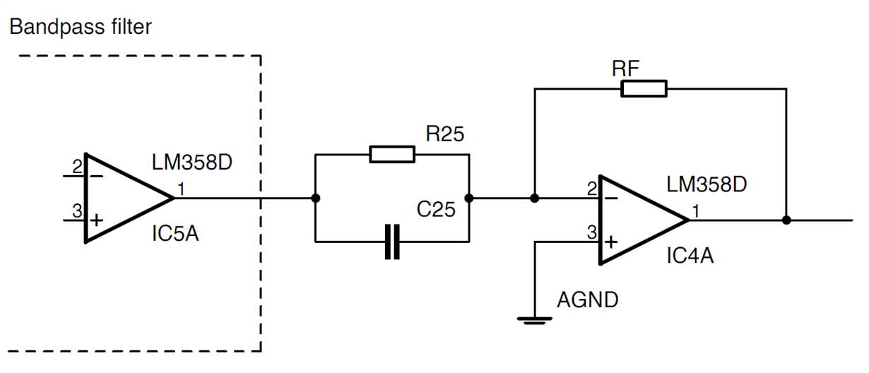
My first idea was to use inverting amplifier OP AMP with capacitor in parallel to resistor....
Any suggestion?
Thanks.

  • Morning Michele, 

    To insert figures, use the paperclip symbol on the ribbon to insert the file holding the image,

    But yes, your BW is so wide that a HP/LP sequence would be normally used. 

  • Hi ,

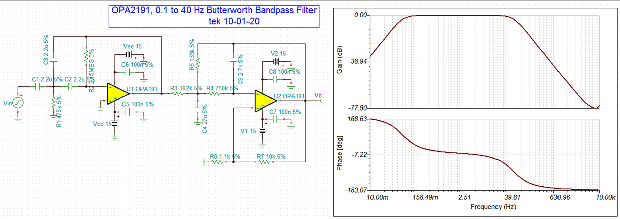
    Enclosed is an example of a HP/LP active filter as Michael'suggested. The BP is from 0.1Hz to 40Hz. If you modify the circuit slightly, it may get what you want. 

    /cfs-file/__key/communityserver-discussions-components-files/14/OPA2191_5F00_low_5F00_freq-Butterworth_5F00_BP_5F00_01-BPF.TSC

    As Michael indicated, please use the icon circled in red to upload image file, use the icon circled in green to upload regular files. 

    If you have additional questions, please let us know.

    Best,

    Raymond

  • Sorry, little misunderstanding, my fault.

    I don't mean I need to design a bandpass filter, I mean I already have circuit working as bandpass filter and I can't change it.
    I need additional block as signal conditioning to cancel pole at -666.67.
    My circuit works as bandpass and I need high-pass from 0.5Hz.

    About images/formulas I know there are buttons to upload images/files, jus I have no way to convert my formulas into images, I need to crop image from screenshot.

  • Hi ,

    Can you post your schematic? All you need to do is to snip the image, save to a file as png, jpg or other image format, then post it. 

    To cancel the pole, you may need add a zero in  (s+666.67), but I am unable to visualize the circuit from the transfer equation. 

    Best,

    Raymond

  • Output block of bandpass filter is op amp, if I correctly remember a Sallen-key but I'm not sure.

    My first idea was this amplifier with zero in RC= 1/666.67

    Next block would be anti-alias filter for ADC, but I don't take care about it now...

  • Hi ,

    Thanks for the additional information. 

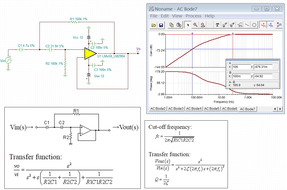
    I back calculated your parameters. Although I did not duplicate your exact circuit, I do see the pole at 0.1Hz and 106Hz. 

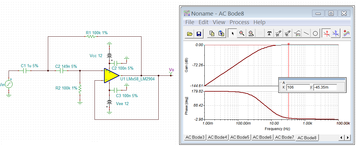
    I believe that all you need to change C1, C2 values and you should get rid of the issues, where the HPF will increase at a rate of +40dB/decade.

    /cfs-file/__key/communityserver-discussions-components-files/14/LM358-Sallen-Key-HPF-10022020.TSC

    Please let me know if this is your issues. 

    BTW, I believe that you are running the filter in series, which means that the circuit is operating in open loop. There are no need to cancel unwanted poles, or zeros, because there are no instability issues in open loop. You only have localized feedback; overall it is operating in open loop. I am making this comments, since I am not sure the reasons that you want to cancel certain poles in your transfer functions. 

    Best,

    Raymond

  • Hi ,

    I was wondering if your problem is resolved. 

    If you have other questions, please let us know. I can convert your remaining transfer functions to a circuit from your schematic block. 

    I am going to close this inquiry for now. If you have additional questions, you may continue to post in the thread, or open a new one. 

    Best,

    Raymond

  • Sorry Raymond, I've been busy in last days.

    Yes, system is open loop, I don't need pole cancellation for stability, but as I said original system acts as a bandpass filter.
    I need pole cancellation to increase bandwidth.

  • Hello Michele,

    The original circuit that you posted having the parallel RC at the op amp input and the feedback resistor will produce a zero at the selected frequency of 666.7 Hz. However, the op amp eventually runs out of loop gain as frequency increases and the gain rolls off with the open-loop gain curve. Therefore, to extend the response provided by the RC circuit the op amp needs high bandwidth. the OPA196 I show has typical gain bandwidth of 2.2 MHz, but other TI op amps have much higher bandwidth which should extend the effect of the zero.

    Here is what I observed from simulating the circuit:

    The gain is +3.0 dB at 667 Hz, and the phase shift is +45 degrees; just as we would expect from a zero placed at that frequency.

    I added C2, the 100 pF capacitor across R2 to reduce some excessive gain peaking that could have lead to marginal stability.

    Regards, Thomas

    Precision Amplifiers Applications Engineering

  • Thomas Kuehl said:
    eventually runs out of loop gain as frequency increases and the gain rolls off with the open-loop gain curve

    So what's happening between 40 and 50 KHz in the graph, right?
    I'll take care about this in a second time, for now I just need to cancel pole then make first tests,
    thanks.