This thread has been locked.

If you have a related question, please click the "Ask a related question" button in the top right corner. The newly created question will be automatically linked to this question.

Low side Phase current sensing for PSMS motor contol

Hello everyone.

I am designing a current sensing circuit for PSMS motor control using the low side Phase current sensing method. The light blue OpAmps in the picture below.

One thing I cannot understand. The three branches current can not be measure for all the status. Even use the Kirchhoff"s law, still only one phase current can be measured when the switch status is 110, 101, and 011. Which 1 is for high side open and 0 is for low side open. It is easy to understand in status 001, 010 and 100. Two branches can be measured and the current of the third branch can be calculated with the Kirchhoffs law.

For example with the status 101. Only the middle branch current can be measured . The other two branches are still unknow in this status. Could someone help me with this? Thanks a lot! Best regards!

  • Hello Xiyao,

    Assuming we're talking about a tradition 6 step trapezoidal commutation where the a High side and Low side are ON, where one phase is floating, current will predominately flow through one of the low side phase current sense amplifiers at a time. The other 2 legs are known, they are just predominantly zero current. BUT, when it is sensed it will look like a square or trapezoid.

    Lets pretend that the tied node below each of the blue low side phase current sensing is not  tied to ground (like it is  in the picture) and that means current will continue to flow through the darker purple low side current sensing amplifier and the RMS current through the motor will be sensed. The shape of current will look more DC (or averaged and added together). If control is done with just the single purple low side current sense amplifier, the control will not be able to differentiate which phase the current came from. This is the benefit of 3 shunt vs. 1 shunt commutation. You can understand where the current is flowing, not just that some current is flowing through the motor.

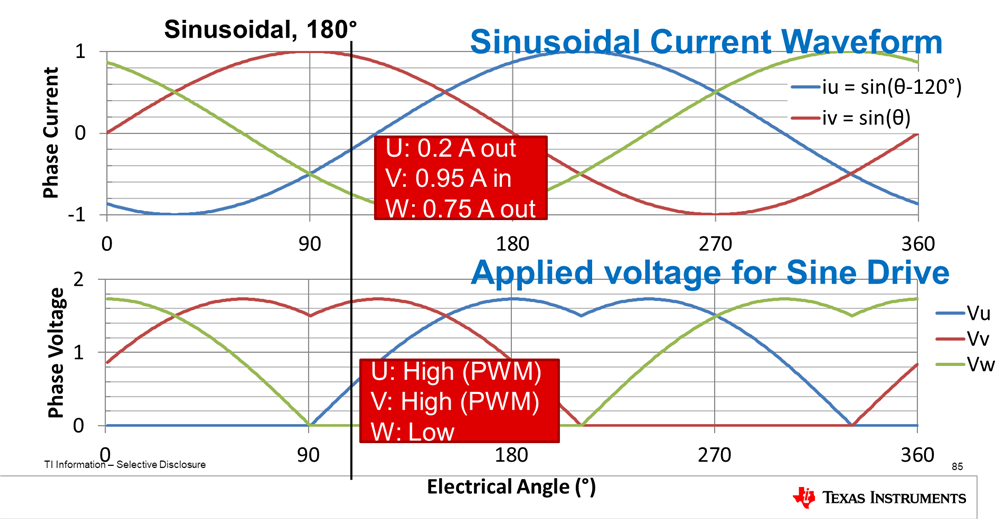
    To expand further, contrast this to sinusoidal commutation. This is where 3 sinusoidal currents (that are out of phase by a 120 degrees) and 2 low sides or high sides with 1 high side or low side, respectively, will be PWM'd to create simultaneous current through all 3 low side phase current sensing amplifiers.

    Hope this helps.

    Best,

    -Cole

  • Hi Cole,

    Thanks a lot for your answer. It helps a lot and I think I understand some.

    I am using this 3 phase low side current sensing circuitry to measure a 3 sinusoidal currents(out of phase by 120 degree) . If it is 110, the 3rd current sensor measures the current, this current lets say I3= I1+I2.( I1 and I2 are the current from the first and the 2 phase, lets say phase 1, 2 ,3 are the branches from left to right, ignore the motor) , so ideally I1 and I2 should have the same value, only 120 degree difference in phase. But it is only ideally, practically they not equal. Still the example 110, only one phase current is measured. The other two low side are 0, but there is current in high side both phase 1 and 2, they are not measured, the value is unknow.  So at least 2 phases have to be measured each time.

    And it is hard to understand that even if there is no current flow through, if measured, a square or trapezoid wave can still sensed.

    Furthermore, the sine wave has + and - so when it negative, it is like high side current sensing, so here a bidirectional current sensor is necessary.

    Thanks a lot! Looking forward for your help!

    Best regards!


    Xiyao 

  • Hey Xiyao,

    Thanks for clarifying that you are sensing sinusoidal current.

    Note, your "1,0,1" or modeling "HS ON LEFT, LS ON MIDDLE, HS ON RIGHT" for the 3 half bridges does not work with sinusoidal commutation. The "1", actually means "apply a PWM duty cycle which exposes the phase voltage that is a percentage of the V_SUPPLY voltage."

    The most common is using the 3rd order harmonic sinusoidal shape for the phase or applied voltage because 2 phases can be applying voltage where 1 lowside can be held low.

    In the example below we can equate your "LEFT, MIDDLE, RIGHT" (e.g. 1,0,1) to instead represent "U, W, V" in the picture. As you can see, the high sides for U and V are "on" but they are of varying their PWM duty cycle (or average applied voltage) and W's low side is "on" to complete your analogy: 1,0,1. I encourage you to draw out 3 phases and 

    For negative current, we need to consider what happens when the applied voltage is <100% duty cycle. Say that we are talking about Vu (the blue line) at this point in time. Let's assume this means the PWM on phase U is ~20% which resulted in 0.2A out of the motor phase. 20% of the PWM high side as "on", this means 80% of time the low side of phase U is ON. To reiterate, we are allowing current to flow through the low side FET because, for some time, the low side is on. This means, current can be sensed only when the lowside is on, and the current through the sense resistor will collapse to 0A when the high side is on

    Note, the reason why current doesn't collapse to 0A through the motor when the low side is on and current is flowing into the motor, is because the motor has L and R. The L will do whatever it takes to keep current flowing in the same direction, even by generating negative Back EMF voltage if necessary to pull current from GND or another phase where current is flowing out, and through the sense resistor and the lowside back into the motor.

    I would highly recommend making a SPICE circuit motor model and that represents this instantaneous point shown in the figure above and plot the voltage across the sense resistor.

    Best,

    -Cole

  • Hey Cole, 

    thanks a lot for your response. I think I had a rough idea and will do some simulations. I would have a deep read about the three phase motor drive. I was a RF EE. Now working at motor control area. A lot of new things have to learn. 

    Could you also recommend me some books or articles in this area?

    Thanks very much!

    Have a nice day!

    Best regards!

    Xiyao

  • Hey Xiyao,

    There's certainly a lot to dig into within these motors. Interesting background, RF seems like a lot too. Glad to help, and continue learning as much as you can.

    We offer a pretty high level course on all things motors called TI Precision Labs (TIPL). that you can find below. We are continuing to add to this series all the time. Feel free to jump straight into the BLDC section. I almost recommend you watch the videos first, get some more understanding, and then come back and watch them again. I recommend this because we talk about the theory and sprinkle the real world cost, tradeoffs, and other advice you won't find in academic papers:

    https://training.ti.com/ti-precision-labs-motor-drivers?context=1139747-1138777 

    For Position and Control in PDF, this one seems to do a decent job

    https://www.ncbi.nlm.nih.gov/pmc/articles/PMC3231115/ 

    For current sense specifically, I've looked at this one before:

    https://scholarsmine.mst.edu/cgi/viewcontent.cgi?article=5580&context=masters_theses 

    Have a fun time spinning motors.

    Best,

    -Cole

  • Thanks a lot Cole.

    That quite helpful!

    Wish you a nice day, month, year and all good!

    Best regards!

    Xiyao Zhao