This thread has been locked.

If you have a related question, please click the "Ask a related question" button in the top right corner. The newly created question will be automatically linked to this question.

INA169: INA169

Part Number: INA169
Other Parts Discussed in Thread: INA190

Dear Experts,

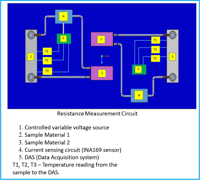
I require help to connect the INA169 sensor to a circuit which goal is to measure the resistance value of the sample 2 and sample 3(see the pic) in different temperature by the help of Data acquisition system(DAS).

I require help on  the physical connectivity of INA169 sensor to voltage supply source ,samples and DAS . 

1.Controlled variable voltage source
2.Sample Material 1 
3.Sample Material 2 
4.Current sensing circuit (INA169 sensor)
5.DAS (Data Acquisition system)

T1, T2, T3 – Temperature reading from the sample to the DAS.

Thanks

  • Amit,

    the images you sent did not come through. Can you please re-upload them using the attach file button rather than copy pasting?

  • Hi Andrews,

    Thanks for informing that the picture of the circuit is not visible.

    For better understanding I am repeating my question again and I have uploaded the diagram in attachment as per your suggestion.

    Will be early waiting for all experts opinions.

    I require help to connect the INA169 sensor to a circuit which goal is to measure the resistance value of the sample 2 and sample 3(see the pic) in different temperature by the help of Data acquisition system(DAS).

    I require help on  the physical connectivity of INA169 sensor to voltage supply source ,samples and DAS . 

    1.Controlled variable voltage source
    2.Sample Material 1 
    3.Sample Material 2 
    4.Current sensing circuit (INA169 sensor)
    5.DAS (Data Acquisition system)

    T1, T2, T3 – Temperature reading from the sample to the DAS.Circuit diagram.docxCircuit diagram.docx

  • Hi Amit,

    how big is the current you want to measure? How big is the voltage coming from the voltage source?

    Kai

  • Amit,

    Thanks for sharing the images of the setup. I am with Kai here, some additional information regarding the planned parameters of the system would be useful:

    - Expected current measurement range (both high and low)

    - Expected common mode voltage

    - Are you planning to implement this on the high side or low side? (i.e., what is the polarity of the terminals of 1)

    - Are there any constraints on the system (power dissipation due to measuring temperature, etc.)

    - Finally, is there a specific reason why you chose to use the INA169? 

  • Hi Andrew,

    Thanks for your queries.

    Expected current measurement range will be in Miliamp range only for both max and min (we are not sure about the exact value).

    Expected common mode voltage -We will be using one voltage source with common ground for all ,so we will have only supply voltage value 5V in respect to ground or zero potential.

    Are you planning to implement this on the high side or low side? (i.e., what is the polarity of the terminals of 1)Kindly see the attached diagram.

    Are there any constraints on the system (power dissipation due to measuring temperature, etc.)...There is probability of heating of sample during current passing through it which we want to measure by DAS.

     Finally, is there a specific reason why you chose to use the INA169? Yes , as the measurement of current though the sample is in mA range ,we want to measure it with minimum error.

    Hopefully I have answered your questions ,will request your guidance to validate the attached circuit diagram and any recommended DAS and it's details for the same.CIRCUIT (1).pdf

  • Amit,

    A few things here:

    - If the range you plan to measure is only a handful of mA's, you may be better looking at an instrumentation amplifier to do this, or a current shunt monitor that exhibits less offset and input bias currents, like the INA190.

    - Apologies, I only saw the first diagram above. Regarding my question as to whether you are measuring on the high side or the low side, if the current flows 1-4-2-1, then you are effectively measuring on the high side, while if the current flows 1-2-4-1. then just the opposite, you would be on the low side. The difference here is what the common mode of the input pins will be. From the second schematic, it looks as though you are measuring on the low side, which means that the input pins will sit at approximately ground. There are tradeoffs to either choice. This video does a great job of explaining the tradeoffs. 

    - Note that if this is the case, this common mode of ~0V <2.7 Vcm minimum of the linear operating region of the INA169. If you did want to use this device, you would need to use it on the high side to ensure you are operating inside the common mode specification. . 

    - The circuit diagram you've attached in the last post as it is will not work. Current shunt amplifiers are a differential measurement tool, and need to be connected differentially across the shunt. The way the schematic is set up, the load current terminates into the IN- terminal of the INA, with no other current flowing path, and this will cause non-linear behavior, if not damage to the device based on the amount of current forced into the pin. You need to ensure that the IN- pin is simply a probe on the load line, and not part of the load line, similar to the below:

  • Hi Andrew,

    Thanks for your reply.

    I have corrected the circuit for high side of current flow.

    Kindly review and share your expert opinion if the attached diagram is good to go with.

    BR//5751.CIRCUIT_20Oct.pdf

  • Amit,

    This is still a low side configuration the way it is wired. The INA should be placed above the sample to be in high side configuration. This way the shunt sees a DC bias of the supply prior to that voltage being consumed by the load. Also, the gain resistor for the INA169 should be placed w.r.t. GND, not placed across the output and DAS. The output of the INA169 is a current, and this voltage will be set by the resistor using Ohm's law. I took the liberty of simplifying and fixing the flow of the diargam. For a high side configuration, you would want something like this: