This thread has been locked.

If you have a related question, please click the "Ask a related question" button in the top right corner. The newly created question will be automatically linked to this question.

INA300: Signal on Rsense

Part Number: INA300
Other Parts Discussed in Thread: TINA-TI

Hi, 

Good day. I hope you are doing well. 

Our customer is using the INA300 and they have the following inquiry. I would appreciate if you could help us with this matter.

"When I test it out, the output of the INA300 signal (pin 5) works. However, the sine wave signal is not being displayed as passing through the INA300. If the detection is working clearly, that means the signal is going through Rsense, so I was wondering why i may not be seeing it on the oscilloscope

The Tina-ti simulation works.(see attached file). Now I am testing out the actual hardware

The signal is a sine wave with frequency 5Hz, peak to peak 5V. It's being driven through resistors (1k bringing current to be 5mA which is over our threshold) and (3K bringing current to be about 1.7mA which is under our threshold). Separately driven to test both instances. Rsense is 10 ohms and Rlimit is 1.22K if you wanted to know

One other thing, when pin 2, on one end of the Rsense, is not connected to ground as shown in the schematic, the signal actually goes through but the sensing no longer works. It's a rather mind boggling problem."
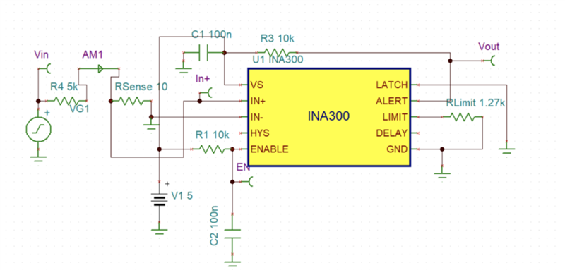

Looking forward to your response. 


Regards,

Cedrick

  • Cedric,

    Using this device to measure currents this low is a challenge. From my calculations, using the 1.27kΩ resistor you've populated for I_LIMIT, the trip point you are setting here is a 24.9mV Vsense, which would equate to a trip point of 2.49mA load current. Sending a 5Vpp sine wave over a 1k/3k resistor, you are effectively sending a 5mApp/3.4mApp sine wave over a 10 ohm resistor to generate a 50mVpp/34mVpp Vsense. This means that the peak voltage you are applying in your simulations is 25mV, which ideally, would just barely be enough to trigger the comparator.

    That said, there is also a worst case voltage offset of -650uV at Vsense, which will add an additional 2.6% error to your measurement due to how low Vsense is, as well as an additional 100uV of error due to the worst case 10uA bias current flowing over the 10 ohm resistor into the IN- pin. From these two errors alone, there is a 3% error margin that you need to take into account, and it is most likely accounting for the failure of the device to trip. A good way to examine this is to place a voltmeter from IN+ to IN- to see exactly what sense voltage the device is seeing, as the voltage at the pins will be what the device acts on, regardless of other nodes in the system (this is true in bench testing as well, and is the best place to start debug). Also keep in mind that there will be other potential errors in the system that will further aggravate this (tolerance of R_LIMIT, tolerance of load resistance, etc.), so you may need to build additional margin over what I've pointed out here. 

    I recreated your setup and ran it, and found that VSENSE was topping out at 24.7mV, which is close, but not reaching your defined limit of the system. Reducing the resistor so that load current can increase, after taking the error into account, the alert pin is pulling low at approximately 2.6mA load current:

    Lastly, the reason the simulation fails when the IN- pin is not terminated is because CSA's differentially sense over the sense resistor, and are not meant to be placed in the ground path. Without a termination to ground on this node, you are effectively forcing the totality of the current into the IN+ and IN- pins of the device and at least causing it to act in a non-linear fashion. In reality, its possible that dependent on the amount of current, it may even damage the pins of the device.