This thread has been locked.

If you have a related question, please click the "Ask a related question" button in the top right corner. The newly created question will be automatically linked to this question.

OPA189: OPA189

Part Number: OPA189

Hi, I would like to use the OPA189 in a mesuemenst system in ABB, but we need to understand better some features about the input impedance. 

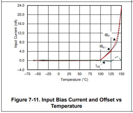
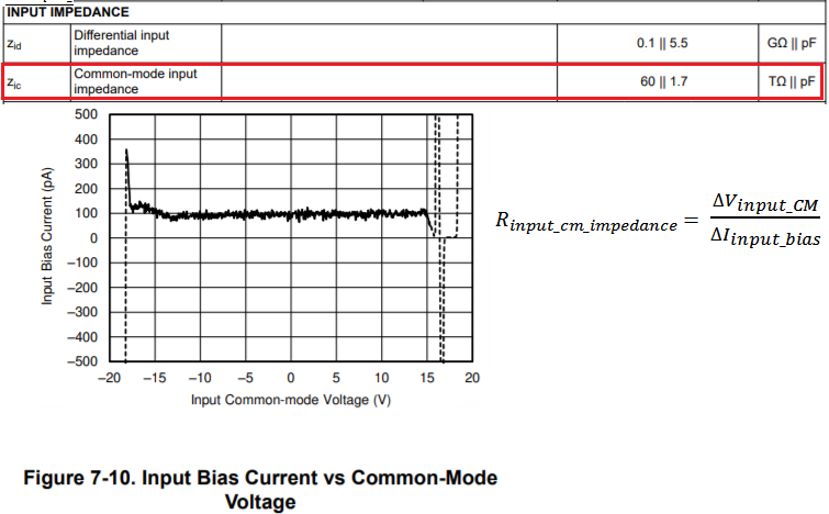
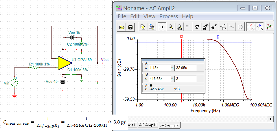
From the datasheet at pag.8, we found the typical impedance specification (resistance and input capacitance ) @25 C° and +/- 18V. We need to know the accuracy of those values (inputs capacitance) and the temperature influence, or maximum value that included the supply, temperature, and other factor dependencies. 

Do you have this information or a metrological characterization of the impedance?

Thanks,

Daniele Gatti.

  • Hi Danile,

    what temperature range are you interested in?

    Kai

  • Hi Kai,

    the temperature range is: -40°C to +70 °C.

    Thanks,

    Daniele.

  • Hi Daniele,

    We do not have metrological characterization of the OPA189 impedance beyond the typical 25 C information provided in the Electrical Characterization table. With the differential and common-mode resistances so high and capacitances so low these usually aren't a significant factor affecting the op amp circuit precision. 

    About the best indicator of the input impedance changing with temperature is the input bias current slope seen in the OPA189 datasheet Figure 7-11, Input Bias Current and Offset vs Temperature. We can see from the graph that the slope increases when the temperature exceeds about 100 C indicating the input real part of the input impedance is decreasing. This is due to the normal leakage current of the input ESD diodes increasing with temperature. You can see how the input bias current behaves with input common-mode voltage in Figure 7-10.

    Regards, Thomas

    Precision Amplifiers Applications Engineering

  • Hi Daniele,

    Q: Do you have this information or a methodological characterization of the impedance?

    Here is the a method to check for the input impedance. In OPA189, the input Rcm is so high, it is nearly a constant vs. input Vcm.  

    Q: We need to know the accuracy of those values (inputs capacitance) and the temperature influence, or maximum value that included the supply, temperature, and other factor dependencies. 

    The input Ccm can be calculated in a following method. First, determine the -3dB frequency with the following circuit, Then, back calculate the input Ccm.

    I do not see the Ccm vs. temperature in the datasheet, but you may be able to compare the setup for 25C and/or an elevated temperature, and see its dependency in a given configuration. Ccm is shown approx 1.7 pF at 25C in the datasheet.  The simulation is estimated approx at 3.8pF. Ccm in 1.7pF is measured figure at 25C according to the circuit configuration presented in the datasheet. 

    The -3dB point with R1=0  in the buffer circuit is approx. 18 MHz. 

    /cfs-file/__key/communityserver-discussions-components-files/14/OPA189-input-capacitance-10202020.TSC

    If you have additional questions, please let us know. 

    Best,

    Raymond

  • Hi, Raymond,

    Thank you for your replay!

  • Hi Daniele,

    together with my information by mail you got a perfect support ;-)

    Thank you Raymond

    Regards Bernd