Because of the Thanksgiving holiday in the U.S., TI E2E™ design support forum responses may be delayed from November 25 through December 2. Thank you for your patience.

This thread has been locked.

If you have a related question, please click the "Ask a related question" button in the top right corner. The newly created question will be automatically linked to this question.

Peak detector Issues

Other Parts Discussed in Thread: TINA-TI, TLV9062

I have designed and simulated a circuit that takes very small sinusoidal signals from a Micro Sensor to an IN AMP (AD8226, Single Supply, 0-5V) and gives a single sine wave output on a +2.5V reference. I then filter and amplify this signal and when I come to convert to DC with a peak detector I get the detection of my signal very quickly but it decays very slowly over a second or two, reducing the capacitance gives an unwanted saw tooth output so there is a trade off here.

Also the bandwidth of this part of the circuit throws my nice response out of the window.

Are there better ways of doing this so I get a quick and smooth response and a quick decay when the signal is removed, taking in mind that my PCB is very small.

The circuit is provided to simulate in Tina-Ti. I have omitted the filtering for a simpler circuit.

Amp.TSC

  • Former Member
    0 Former Member

    Hello David,

    Thanks for your questions.  I have taken a look at your schematic and have a couple follow up questions for you.

    As the circuit is given, I actually do not see a long term decay.  There is decay over a few milliseconds, but not on the scale of several seconds.  Would you please clarify under what scenario you observed this?  Would you also please clarify how the bandwidth of the parts "throws my nice response out of the window"?

    Looking forward to your responses so we can get this all sorted out quickly.  Also, here is a more complex implementation of a peak detector in case you are curious.

    Peak Detector.TSC

    Regards,
    Daniel

  • Former Member
    0 Former Member

    Hi David,

    We haven't heard back from you in while.  I hope this means your question has been resolved in some manner.  Please let me know if this is not the case and/or there is anything I can do to help.  Else, I will consider the matter to have been resolved.

    Regards,
    Daniel

  • Sorry about the late reply, illness, crazy times we are living in.

    I built the circuit which detected my sensor immediately but when the input signal was removed the output signal decayed over a few seconds. I put an Led on the output as well to see the effect better, I did simulate this with a pulse instead of a sine wave and it gave me the same thing but I did this with an input signal of 10mV before the In-Amp which was why I saw the output signal decay for so long.

    This was when I was using the AD8422, the resistor I used for this gave me a gain of 150, the resistor in the simulation should be 330R for a gain of 150 and the actual gain is about 438, too high.

    Also I believe I am getting a far higher signal from the input sensor as well and it is sensitive to sources from the surrounding environment due to the small signals I am amplifying. I believe I need to dampen the input signal more.

    The circuit you suggest looks good but I am using a single supply.

    There must be a better way to convert a small sine wave to a DC voltage for a single supply?

    Regards

    Dave

  • Hi David,

    what is the amplitude range of your sine signal at the input of rectifier?

    Kai

  • The output of the In Amp will be a minimum of 7.5mV with the input offset at 50uV in the datasheet.

    So I want to take the range from 10mV to 50mV or 100mV. The input is sensitive, I may need to reduce the signal before it gets to the In Amp so I get a more consistent output range.

    Thanks

    Dave

  • Former Member
    0 Former Member in reply to Dave

    Hi Dave,

    Not a problem.  Hope you are doing well and just wanted to make sure we'd done whatever possible to help.

    In taking a look at my circuit, you are correct.  The circuit will only work for dual-supplies assuming the input has both voltage polarities.  My apologies for the oversight.  In fact, some of the other peak detector circuits I found will have the same issue.

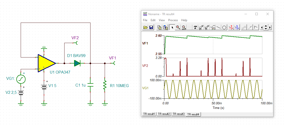
    As shown here, your peak detector is almost like a sample and hold of the peak voltages.  In other words, the size of the output capacitor is going to determine how well the "DC voltage" is held.  You can always make this bigger to give you a more steady voltage (less droop).  Have you given thought to how much droop is permissible?  If it is somewhat ok, then bumping the size of the capacitor may give you sufficient results.

    Another possibility is to do a full wave rectification followed by a different peak detector circuit, such as the one I showed above.  The concerns here would be the increase in component count and signal linearity so close to GND.  It might be best to do In Amp -> Full-Wave rectification -> Gain Stage -> Peak Detector.  Again, this may be more complex than desired.  Perhaps Kai knows of a more simple solution.

    Regards,
    Daniel

  • Former Member
    0 Former Member in reply to Dave

    Hi Dave,

    Just want to make sure that we've done whatever possible to help you here.  Let me know if you have any remaining doubts or I will assume you've found a solution.

    Regards,
    Daniel

  • Hi Dave,

    it's very difficult (if not impossible) to build an accurate peak detector with a micropower OPAmp showing a rather limited bandwidth:

    The much faster TLV9062 suggested by Daniel can do it much more precisely:

    Kai

  • Hi David,

    you could do it this way:

    david_opa347_1.TSC

    Kai