


Other Parts Discussed in Thread: OPA564
Hello there,
For the last couple of days I have been working on OPA548 power opamp and could not tackle the instability issue. I am using the opamp to push current across the electrodes dipped into conductive water. Since the conductivity is high, we are talking about resistance levels below 100 Ohms. On the breadboard I build inverting amplifier with the gain of 3 (refer to figure 1). I have all decoupling connected as suggested in the datasheet. When the load is connected (30 ohm) I do get ringing on the negative side of the waveform. It's oscillation frequency is around 1MHz. I have tried snubber method - does not reduce the ringing, since I use low resistor. My opamp is powered by +-5V power supply. The input waveform is 1Vp-p at 10kHz and output is 3Vp-p. The lowest load is designed to be 15 ohm reference resistor in series with electrodes (thus it never gets short), max current = (3V/1.41)/ 15Ohm = less than 150 mA. Figures 2 and 3 shows the instability at different frequencies having the same 30 ohm load.
I am aware that open loop GBW is 1Mhz, thus I selected this opamp knowing that there will be plenty of space for minimal gain of 3 and operation at 10kHz. Interestingly enough. when the load is much higher, say 10 kHz, opamp performance is brilliant even at 100kHz. However I need to drive small loads. Figure 4 shows this case on the oscilloscope.
Could you guys please assist me on this issue? What are the options to stabilise the opamp even with low resistance loads? Is this opamp a good choice for such application? Do I need to add a current boost stage with a pair of pnp and npn transistors (although I don't think it is lack of current problem)? Looking forward to any advices and assistance.
Kind regards,
Tadas

Figure 1: schematic.

Figure 2: Oscillation of the output at 42kHz with the load of 30 ohm
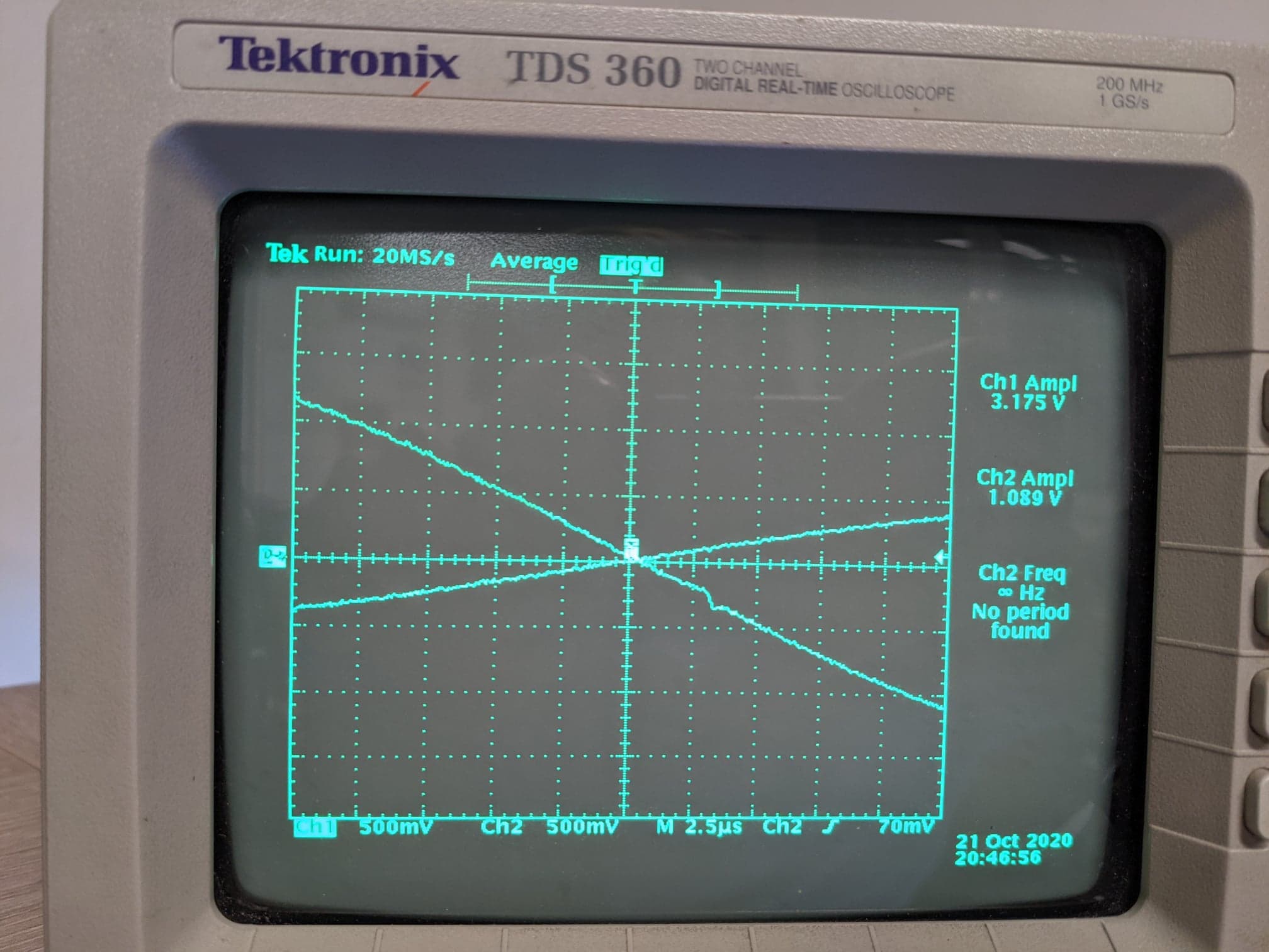
Figure 3: Oscillation at operating frequency 10kHz with the load of 30 ohm.
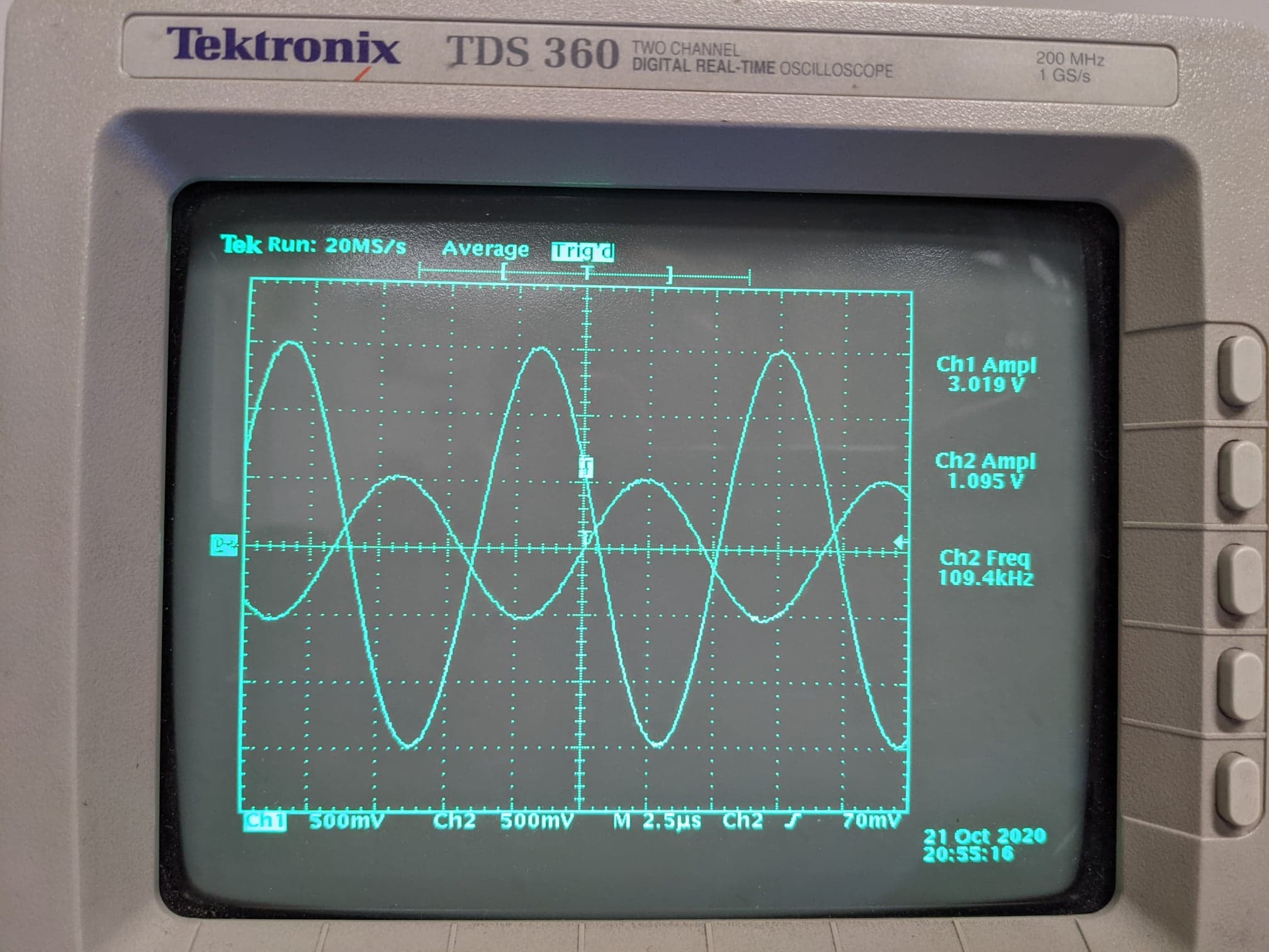
Figure 4: Good opamp performance with the load resistance of 10 kOhm at the frequency of 100kHz.


