This thread has been locked.

If you have a related question, please click the "Ask a related question" button in the top right corner. The newly created question will be automatically linked to this question.

INA821: Problems with the PSPICE model

Part Number: INA821
Other Parts Discussed in Thread: INA828

Hello,

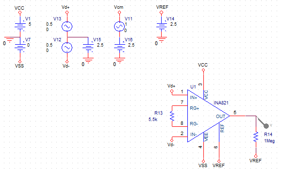
I want to implement the INA821 in a single supply application, setting the Reference to middle range. So I did some simulations to evaluate the model (using PSPICE 17.4) and was not able to converge the AC simulation in any way using the following circuit:

However, using dual supply (+2,5V -2,5V) and setting the reference and DC common mode voltage to zero, the simulation worked just fine (although some second order deviation from the datasheet curve occurs after 10 MHz - see Figure). 

Am I missing something here or is there a problem with the PSPICE model? The datasheet allows 5V single supply, so I don't know what's the problem here.

Thank you,

Kaue

  • Hi Kaue,

    Please take a took at the simulation below. With 5V single rail supply, the input Vcm has certain constraint. 

    /cfs-file/__key/communityserver-discussions-components-files/14/INA821-E2E-10222020.TSC

    If you have additional questions, please let us know.

    Best,

    Raymond

  • Hi Raymond,

    Thank for the fast response.

     The problem is that my schematic is basically the same as yours (except for the R1 resistor) and the circuit does not converge. I believe you used TINA in this transient simulation, and I'm using the PSPICE AC simulation. When I shift to a symmetric supply (with the same supply range) and ground the reference the simulation converges.

    PS: That Vcm source in my schematic is doing nothing in this particular circuit. The input common-mode is a constant 2.5V, as well as the reference. I should have removed the Vcm source from picture.

    Best regards,

    Kaue

  • Hi Kaue,

    AC analysis usually allows only one input source. But you have three in your schematic.

    Kai

  • Hi Kaue,

    I am not sure if Kai and I are answered your questions. 

    In your circuit, you have the following input configuration, and the INA821's differential input is 1Vp-p. The circuit gain=10, so that was the part of the reasons why it is not working. When you are using +/-2.5V dual supply rails, I do not know what was the differential input. If the input 1Vp-p is used, it will not work either. In my previous simulation, I use 100mVp-p as input. 

    FYI, please use the icon circled in red to upload image file, and use the icon circled in green to upload other standard file. 

    If you still have the questions, please post the file that you had questions in. 

    Best,

    Raymond

  • Hello Kai,

    That's actually not true, at least for PSPICE 17.4. I can use multiple AC sources in AC simulations and it works just fine.

    Thank you for the response, 

    Kaue

  • Hi Raymond,

    This is true for transient simulations, but the models in PSPICE AC Sweep simulations are linearized (small signal), so saturation is not considered. I typically use 1Vac for AC sources, so the output is already the circuit gain.

    In the dual supply simulations I used the same input amplitude.

    I reduced the input amplitude of the single-supply circuit anyway and was still not able to converge the simulation. 

    Best,

    Kaue

  • Hi Kaue,

    Can you send me the work file? I think that you have to zip the folder and change the *.zip extension in order to get through the server. 

    I am not aware of any pspice model issues in the part.

    BTW, are you checking on the BW of the INA821? Also, can you post the missing image file initially. 

    Best,

    Raymond

  • Hi Raymond,

    Sure, I'm attaching the .zip file: INA_TEST.rar

    The second image was for the dual supply case. After 1MHz, there's this second order effect that is not apparent in the datasheet gain curves:

  • Hi Kaue,

    Can you rephrase your inquiry again? If I understood your question correctly, you are saying that you are able to perform the AC analysis with dual supply voltage rails. However, you are encountering AC analysis converge issues, when a single supply voltage is used. Am I understand your issue correctly? Or you are questioning the zero and pole that is located at approx. 5.1 MHz. 

    Below the AC simulation with 5V supply rail in Tina, which is the same AC response as the image above. 


    Best,

    Raymond

  • Hi Raymond,

    My main problem is the convergence issue when using single supply and middle-range reference. 

    The single/pole at 5MHz is just another question that I had, because it didn't completely matched the datasheet.

    Best,

    Kaue

  • Hi Kaue,

    Ok, I will get it back to you on Monday. 

    Best,

    Raymond

  • Hi Kaue,

    Q: The single/pole at 5MHz is just another question that I had, because it didn't completely matched the datasheet.

    The INA821's datasheet of 4.7MHz at Gain=1 is correct. However, I think that the PSpice model did not taken into account the BW at Gain=1 (Rg=infinity R)

    Here are the reasons. 

    At Gain=1, the BW in simulation is measured at 2.16MHz (I am using -3dB at the cutoff reference, even though the the roll off is approx. -40dB/decade).

    At Gain=2, the BW in simulation is measured at 2.13MHz  (no figure in the datasheet).

    At Gain=10, the BW in simulation is measured at  1.86MHz (datasheet is shown 970kHz).

    First of all, the BW can not be the same with Gain=1 and Gain=2, because it will violate Gain Bandwidth Product rule for -20dB/decade instr. amplifier's analog front end stages. INA821 is shown as 3 op amps instrumentation amplifier configuration per the datasheet. 

    Here are 3 op amp Instr. amplifier's BW characteristics. 

    1. The BW of analog front end of two op amps doubles at the first differential input stage (up to its unity gain BW). For instance, it total instr. amplifier gain=10 V/V, each op amp contributes 5V/V at the first stage of 2-stage instr. amplifier. And two front end op amps roll off at -20dB/decade.  

    2. The BW last stage of differential op amp reduces  by the third op amp, because of difference amplifier, and the final roll off will be product of front end, which it is decreased at a rate of -40dB/decade. 

    3. Final BW of instr. amplifier seems to be higher because of the Q, which is extended the actual BW of the third op amp. I think that INA821 uses three identical op amps in the design. 

    Based on the above characteristics, with Gain=2, the measured BW of 2.13MHz, which is correct. With Gain=1, the BW of the INA821 should be double of 2.13MHz or approx. 4.26MHz, The datasheet is shown approx. 4.7MHz (This is measured figure during IC characterization).  

    If we use Gain=10 example, the datasheet is shown 970kHz, The BW of each op amp is approx, .970MHz*5 = 4.85MHz, which it is in agreement with above example. 

    Thus, the PSpice model in BW simulation has issues. 

    Q: My main problem is the convergence issue when using single supply and middle-range reference. 

    I have the same findings as you have. With symmetric dual power supply, the Cadence simulation works fine. If I change the symmetric power supply slightly, say Vcc=12Vdc, Vee=-10Vdc, then the tool crashes and encounter convergence issues. I do not see the mid-range is an issues in the simulation. As soon as I changed the Vee different from Vcc, the Cadence tool does not like it. 

    I do not know the reasons, so I may submit an inquiry to Cadence support team. 

    As you have seen, I do not have any issues when I simulate with Tina Tools. In addition, I changed the instr. amplifier from INA821 to INA828, I am observing the same convergence issues in Cadence 17.4 version (PSpice for TI tool). So I do not believe that this is INA821's model issues.

    If you have additional questions, please let us know. 

    Best,

    Raymond  

  • Hi Raymond,

    Thank you for the effort and support. Also, the BW explanation was very enlightening.

    If you heard from Cadence about this issue, please contact me.

    Thank you very much,

    Kaue

  • Hi Kaue,

    I submitted the inquiry to our PSpice model engineer, and I learned that the convergence issues are the model issues in PSpice tool chain only. It works fine in Tina simulation tools.  The engineer is suggesting that we are using Tina simulation for now. I do not think that it will be a quick fix. 

    Anyway, if you need additional assistant, I can simulate it for you and send you the results. 

    Best,

    Raymond

  • Hello Raymond, 

    Thanks for the the response. I understand that its probably something not easy to fix.

    Best regards,

    Kaue

  • Hi Kaue,

    Regarding to the INA821, you are able to simulate with symmetric power supply rails (with equal voltage, but opposite polarity). The model still works with Vref offset voltage. So if you elevate Vref, say 2.5V over +/-5V rails, the simulation result will be still the same.

    Once you have the revised model, then you can change the simulation to single power supply configuration. 

    Best,

    Raymond