This thread has been locked.

If you have a related question, please click the "Ask a related question" button in the top right corner. The newly created question will be automatically linked to this question.

XTR111: XTR111

Part Number: XTR111
Other Parts Discussed in Thread: TL074, TLV9001, TL072

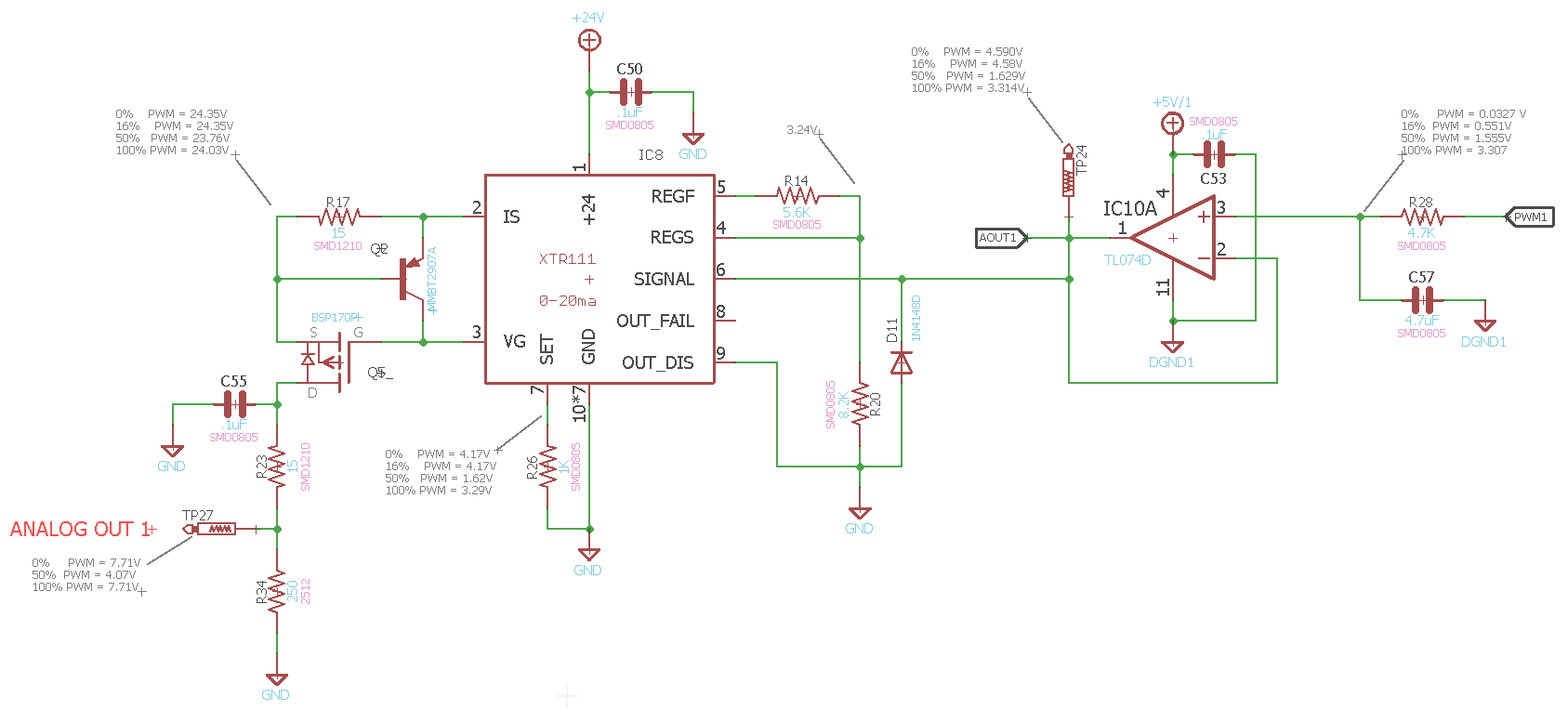
I designed a 0-20mA transmitter based right on the Application block diagram Fig 46 out of the XTR111 Datasheet with the exception of using a PWM signal as the VIN voltage.

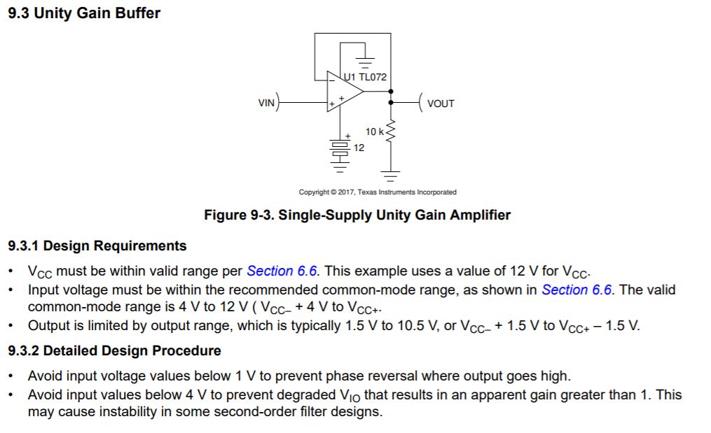
This PWM is beign filtered by a 4.7K over 4.7uF cap RC filter then goes through a voltage follower (Unity gain OP amp). The voltage comes out to .03V at 0% PWM to 3.307V at 100% PWM.

This voltage is passed into pin 6 of the XTR111.

The output voltage at the output, which is connected to a 250ohm 1/2W resister is 7.71V at 0% PWM, 4.07V at 50% PWM, 7.71V at 100% PWM. (wacked out) that translates to 30.8ma @ 0%, 16.2mA at 50% and back to 30.8mA at 100%.
I calculated Rset to 1.5K for a 3.3V input.

I'm not using the built in regulated but I put a 5.6K over 8.2K to regulate at 3.24V

Schematic with readings below.

  • Hi Leonard,

    Thank you for providing the detailed schematic with your readings. It looks like you are using a 1k resistor in your schematic as your Rset and not 1.5K. It looks like the XTR111 is preforming as expected for the Rset of 1k with the input values coming from the output of the buffer, and maybe hitting the current limit where you see the 30.8mA. I believe you are violating some of the conditions of the TL074. The common mode range is Vcc- +4 and Vcc+. So with your single 5V supply, that puts you at an input range of 4 to 5V for a buffer configuration. The output voltage is Vcc- +1.5V to Vcc+ - 1.5V, which gives you a range of 1.5V to 3.5V. The datasheet of the TL074 has a section on a single supply unity gain amplifier and it says to avoid values below 1V to prevent phase reversal where the output goes high. I think this is what you're seeing on the 0% and 16% voltage outputs of the TL074. 

    You'll need to choose an op amp that has a common mode voltage range that fits your input values.

  • Hi Leonard,

    I agree with Katlynne. The TL072 is unsuited in your application because it's no rail-to-rail OPAmp. Take the TLV9001 or another RRIO (input outout rail-to-rail) OPAmp. Also, increase C53 to > 470nF.

    Kai

  • I agree, I ordered a OPA4340UA to replace the TL074s and now the drive is linear.

    Now I just need to retune the XTR111 for a 3.3V max in (100% PWM) i'll probably back the setting to 3.1V for some headroom.

  • Hi Leonard,

    Great to hear that you're seeing the linear output now. Please let us know if you need any other assistance.