


Part Number: INA250
Hi team,
I have a customer planning to use the INA250 for current sensing across 4 different switchers.
the schematic is equivalent in all cases, but the INA250 family selected is different.
can you please help to review the schematic and let me know your feedback?
switcher 1:
Vin = 12V, Vout = 4.7V, Iout = 0.88A
INA250A4 selected.
switcher 2:
Vin = 12V, Vout = 20.7V, Iout = 2A
INA250A3 selected.
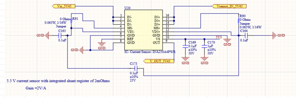
switcher 3:
Vin = 12V, Vout = 5.5V, Iout = 1.23A
INA250A4 selected.
switcher 4:
Vin = 12V, Vout = 3.8V, Iout = 3.8A to 4A.
INA250A2 selected.
Thanks,
Kevin
