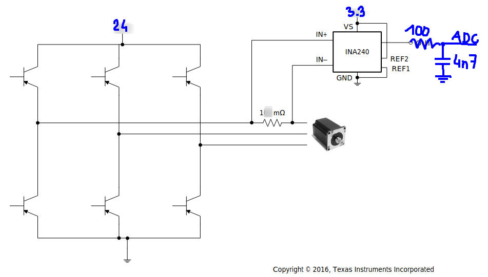
Other Parts Discussed in Thread: TIDA-00643
Hello!
I have several questions about INA240 (specifically A1 or 20V/V) as in-line current sensors in sensorless FOC.
My motor application is ~600-800W, 24V, 30-35A battery current, up to 60-80A Q-axis current when accelerating, up to ~100% PWM modulation, 30-60kHz switching frequency. The motor is PMSM 23mOhm, 27uH, 2.9mWb.
1: PCB Layout: Is it better to place INA240 sensor close to shunt resistor (0-5mm) and route amplified signal (30-50mm) to ADC or place the INA240 close to ADC which results in longer, but differential unamplified signal?
Unamplified signal is +/- 80mV, amplified 0 - 1.65V - 3.3V. Board layout is quite dense, so the signal is passing through/close to power stage. It's quite similar to TIDA-00643 reference design.
2: PWM Rejection: From INA240 datasheet it seems at first, that positive PWM edge results in a bit worse amplifier output swing than the negative one:
But later there's another capture with huge spikes on negative PWM edge and it seems positive edge is better:
So my question is: which is the real one? And Is it better to sample the phase current signal at negative pulse - 0V (like low-side), at VM (high-side) or mix both?
Currently, measurements are taken in the middle of the PWM pulse, but when modulation is high enough, the measurement can result close or even at the switching edge.
Is it okay to trigger ADC measurements on the Timer UP/DOWN updates or extra care should be taken to trigger it in the right moment depending on the modulation?
3: Does INA240 output swing depend on output filter components? In the DS it seems, that the output swing settles in about ~1.5us. In my application the swing takes at least 2.5us.
And here is my application:
4: Also some more InstaSpin FOC related question: What happen to InstaSpin FOC ROM estimator if one of the current measurements saturate?
In my application i use 1mOhm shunt + 20V/V amp gain, so the measurable range is (-82.5A, +82.5A). I think it should be best compromise between low-load performance and usable range, as it seems it should be enough for the motor and 600-800W power. Next possible values could be 0.5mOhm shunt,20V/V gain with the (-165A, +165A) range, but then it's unnecessarily too large and the low-load signal will be noisier.
In (-82.5A, +82.5A) option it is possible that in some current spike cases the amplifier could saturate. Could it potentially destabilize InstaSpin estimator and eventually result in smoke or fire?
Best regards!
Mateusz

