This thread has been locked.

If you have a related question, please click the "Ask a related question" button in the top right corner. The newly created question will be automatically linked to this question.

INA301: To understand Gain error of the amplifier at different load conditions

Part Number: INA301

Dear ALL,

Please provide the following information for the INA301 current sense amplifier,

  1. The datasheet specifies max gain error as 0.1%, is it for full scale load measurement with respect to all conditions like temperature, voltage at different ranges?
  2. Is there any test results available for different load measurement ranges i.e., load @ 5%, 10%.... 100%? It is to understand the gain error at different load conditions.
  3. Gain error at different operating temperature conditions from -45 to +85 degree Celsius.

Thanks,

Santosh.

a.       Error (%) or mA in full measurement range and at 25 degree Celsius

  • Santosh,

    Thanks for choosing TI. The gain error for the INA301 over temperature is given in the electrical specifications table on page 5 of the datasheet:

    Q1&Q3: A few things here: the 0.1% that you mention is only for the A1 variant of the device, and is for room temperature condition. To examine the effects of temperature on the gain error, you need to examine the last entry, which shows gain drift over temperature in the worst case amount of 10ppm/deg C. This means that for every degree of temperature increase (or decrease), the gain will change by X (the easiest way to convert ppm to percentage is to multiply the value by 1E-4). So for example, at the maximum temperature of 125C, the worst case gain error for the A1 variant would be 0.1% + 10*1E-4*(125-25) = 0.2%

    Q2: Unfortunately we do not characterize the device over multiple load types, so this data is not available. 

    Also, I would advise you to check out our video on gain error for additional information on this topic here

  • Hi Carolus,

    Thanks for the replies.

    Our requirement is we want to measure 0 -10A load current @ 0.1% accuracy and we have chosen INA301A1 and 10mE(CSM3637, 3W) resistor.

    Can you please let me know what could be the minimum current we can measure with the 10mE(CSM3637, 3W) resistor (with 0.1% accuracy) AND INA301A1?

    Basically we want to understand that can we measure 1mA current variation in the load? what is the best resolution we can achieve and how to calculate the same?

    Thanks,

    Santosh.

  • Hi Santosh,

    remember that you can do lots of calibration and correction of errors in your µC software :-)

    Even a temperature compensation could be carried out.

    Kai

  • Hi Kai,

    I agree with your comments.

    We are trying to gather best possible pre-design information that are already available from TI or the device Users.

    Hope you understand and provide the inputs required.

    Thanks,

    Santosh.

  • Santosh,

    To achieve these levels, I agree with Kai that you are going to have to perform a calibration of the system, and even then it may be challenging. There are a few  issues to consider here:

    1) Amplifiers can face challenges when trying to measure directly down to 0A. All amplifiers come with some form of offset voltage, and as the measured current approaches zero, the amount of sense voltage generated by the shunt also approaches zero, and therefore the offset dominates the measurement. With your 10mΩ resistor here is what the error curve looks like as you move towards zero amps. Note that I have stopped at 100mA to make the curve somewhat readable:

    So at a measurement of 350mA, you are already at 1% error, when your target is 0.1%.

    2) Examining the same curve, you can see that at room temperature, the y-asymptote of the curve itself is the gain error of the device. As the signal must pass through the device, at full scale range, the best you can ever do is the gain error of the device, which for the A1 variant is your 0.1% target. Temperature will exacerbate this value. 

    3) A measurement directly down to zero is not achievable, as the amplifier exhibits a swing to rail limitation at ground:

    If the amplifier is driven below this condition, it will saturate the output will become non-linear. Also, as the amplifier is driven back into the linear region, there may be recovery effects/timings that may or may not be important based on your system requirements. 

  • Hi Carlous,

    Thanks for the report.

    Can you please share the tool used for the calculation to calculate with different resistor ratings and generate the report for our analysis.

    Regards,

    Santosh.

  • Santosh, 

    The tool I used above is the Current sense amplifier error analysis tool, and can be found about halfway down the product page of the INA301 (or almost any device for that matter). 

  • Hi Carolus,

    We have tested the boards and the output of the INA301A1 is 0.859V at the load current of 10A but it should have been 1V as per the datasheet and the

    formula(10A x 5 mΩ x 20 V/V =  V).

    As per the datasheet of INA301A1 below are the expected results from the INA301A1,

    Sl.No load Current(A) Expected INA301A1 output(V)
    1 0.5 0.05
    2 1 0.1
    3 1.5 0.15
    4 2 0.2
    5 2.5 0.25
    6 3 0.3
    7 3.5 0.35
    8 4 0.4
    9 4.5 0.45
    10 5 0.5
    11 5.5 0.55
    12 6 0.6
    13 6.5 0.65
    14 7 0.7
    15 7.5 0.75
    16 8 0.8
    17 8.5 0.85
    18 9 0.9
    19 9.5 0.95
    20 10 1

    Please do the needful.

    Thanks,

    Santosh

  • Hi Santosh,

    the most mistakes happen with the reference measurement of load current and with the shunt itself (soldering, layout, etc.). Sometimes even taking the wrong the shunt resistance is the cause.

    Can you show your layout of INA301 section? And how did you carry out the reference measurement of load current?

    Kai

  • Santosh,

    I agree with Kai here. A schematic and layout would be useful to help diagnose the cause here. 

    In addition to Kai's comments, a common error also often overlooked is the choice of filter resistors as discussed in section 7.4.1 of the datasheet. If a resistor value >10Ω was used, I would expect the gain of the device to be reduced, and therefore you would see a reduced voltage on the output. 

    Please let us know if you can share your schematic and layout.

  • Hi Carlous,

    We have used 10Ω for filtering.

    Please share your email ID to share the schematics.

    Thanks,

    Santosh,

  • Hi Santosh,

    is this thread connected to this one?

    Kai

  • Hi Kai,

    Yes both are connected.

    Thanks,

    Santosh.

  • Hi Santosh,

    I ask because the shunt resistances are differing from each other in both threads.

    Kai

  • Hi Carlous,

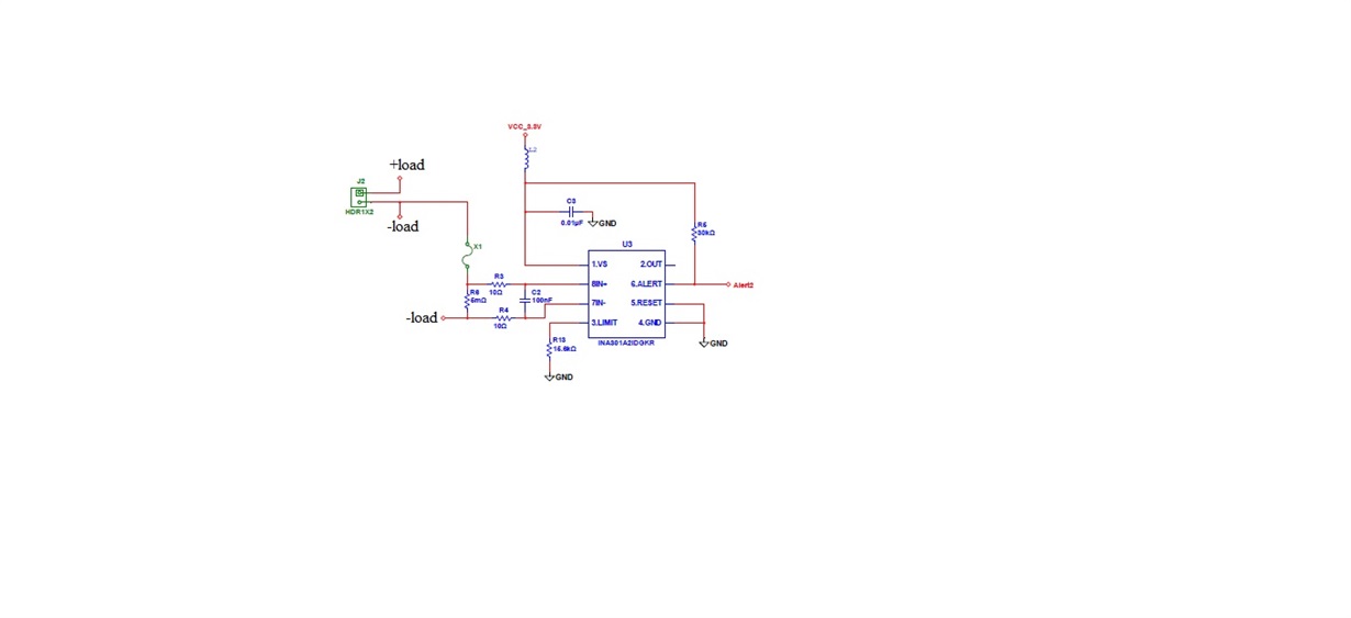
    Please find the schematics below,

    Thanks,

    Santosh.

  • Hi Carlous 

    Attached the schematics.

    Thanks,

    Santosh.

  • Hi Santosh,

    the schematic didn't come through. Please use the "Insert File" button (paper clip).

    Kai

    EDIT: Ok, now we can see it :-)

  • Hi Kai,

    Hope you can see it now.

    Thanks,

    Santosh.

  • Santosh,

    After reviewing the layout and schematic, I have a few follow-up questions:

    - On the schematic side, it appears both sides of the shunt are the same node (-load). I'm assuming this is not correct?

    - As Kai mentions, in the layout post, there seems to be a conflict between data table and schematic of the shunt value, but I am assuming it to be 5mΩ. Would it be possible to get an exact value of the shunt populated under test?

    - Have you attempted to fix the 2-wire vs. 4-wire layout issue pointed out by Kai and Javier? At higher current levels, the sensing error effects of solder joints will become more apparent, and the sense lines help to maintain accuracy in this type of shunt resistor. I believe this could be a contributing factor here. 

    Are we certain that the load current is generating the sense voltage we expect, and that that sense voltage is making it to the pins of the INA301? To help narriw this down, can you run a retest on a few data points, but during this test,

    1) Probe the voltage being generated across the shunt 

    2) Probe the voltage seen directly at pins 7 and 8 of the device 

    3) Probe the corresponding output voltage. 

    This will help us see what is going on here. 

  • Hi Carlous,

    We are measuring short circuit current and resistor value is 5mE.

    We measured across current sensing resistor on the 4 terminal resistor and the results were same. It looks like we need to construct new PCB's for better results.

    1) We measured the voltage at OUT pin of the INA301 and we are getting 498mV for 5A load.

    Thanks,

    Santosh.

  • Santosh,

    Understood. If the problem persists once you fix the sense lines on the resistor layout, please reach back out for additional support. I will mark this as resolved.