This thread has been locked.

If you have a related question, please click the "Ask a related question" button in the top right corner. The newly created question will be automatically linked to this question.

TLV9002: TLV9002SIRUGR operation problem

Part Number: TLV9002

Hi,

There is an operation problem during the test after PCB fabrication, so please contact us.
If the PA6 pin of MCU is High and all other pins are Low (including power), USB connection is not possible.

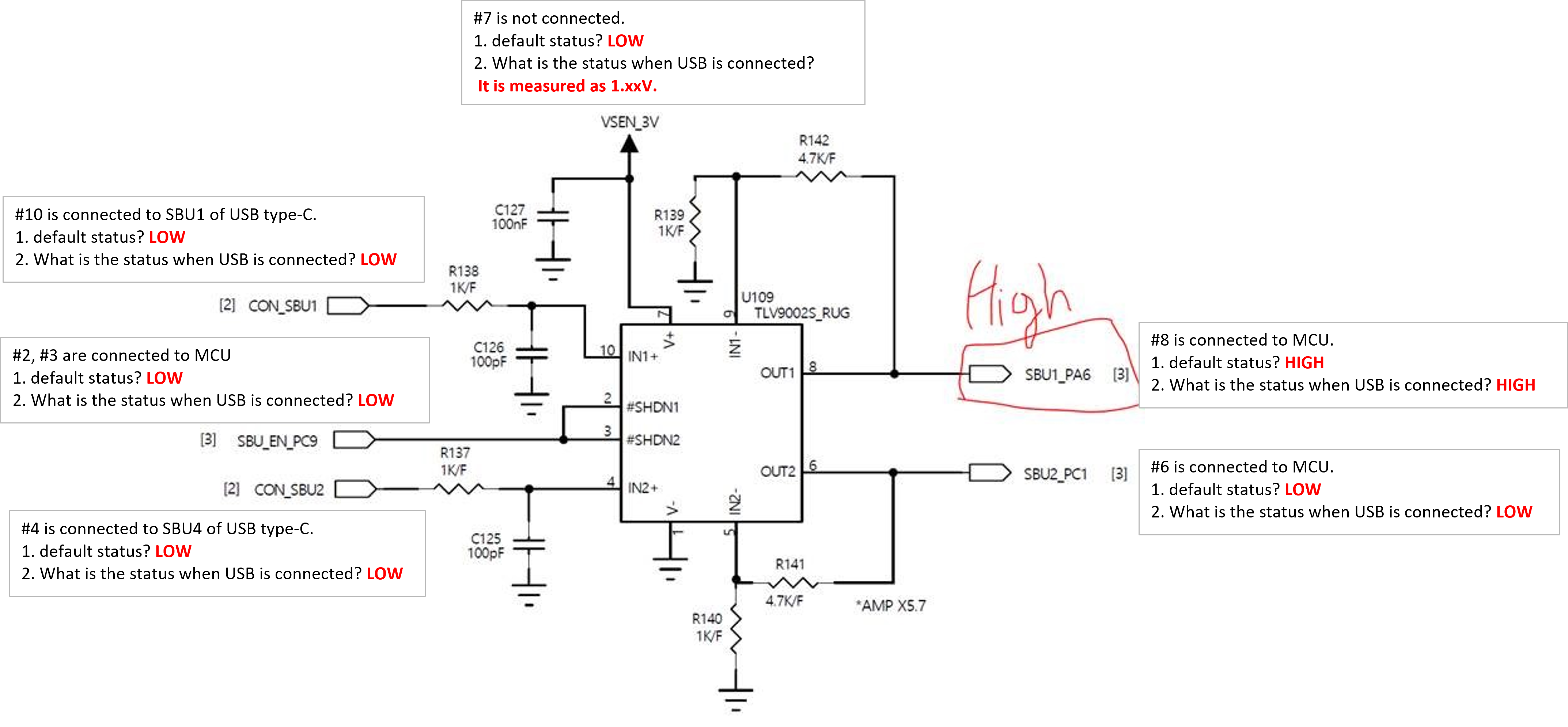
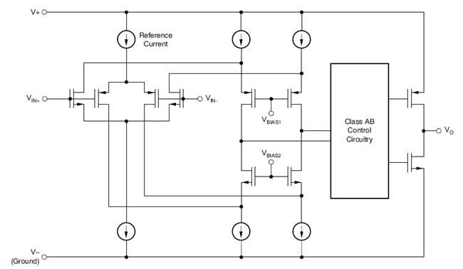
When I check the block diagram of the datasheet, the output is connected to the input, and when I check V+, 1.xx V is floating.
When the part is removed, it is directly connected to USB, and even when 3.0V is connected to V+, it works normally.

I would like to know the cause of the reason why the level of 1.xxV is measured in V+ and USB connection is not possible due to this.

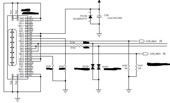
The circuit diagram of the USB type-C connector connected to the TLV9002S is as follows. Please refer.

Thanks,

MJ

  • The absolute maximum ratings (section 7.1 of the datasheet) do not allow this. Footnote (2) says:

    Input pins are diode-clamped to the power-supply rails. Input signals that may swing more than 0.5 V beyond the supply rails must be current limited to 10 mA or less.

    Current flows from the input pin into the power supply and partially powers up the opamp.

    You must not power down the opamp while input signals above 0 V are possible. Use an opamp with shutdown (like the TLV9002‍S), or add an analog switch that can disconnect the inputs.

  • Former Member
    0 Former Member

    Hello MJ,

    Clemens is correct.  If the device is completely shut down, you do not want to be driving the input and output pins.  These pins have diodes to both rails, as shown below.  When you drive the pins and the rails are at ground, the ESD protection diodes can turn on and send current from the input or output to the rails.  One consequence of this is that the voltage of the rail can be pulled away from GND.  Additionally, the ESD diodes are not meant to handle these long-term currents.  So, this can affect part reliability or even lead to damage.

    One solution you might consider is to keep the V+ rail powered so that the input voltage does not exceed this rating, but keep the SHDN pin pulled low to disable the amplifier.  This will minimize current consumption while protecting the part.  If you have questions about the shutdown functionality of this device, we have an application note just on this topic.

    Regards,
    Daniel

  • Former Member
    0 Former Member

    Hi MJ,

    Since we have not heard back from you, I hope your issue has been resolved.  Please let me know if you need any further assistance with this problem.

    Regards,
    Daniel

  • Hi, Daniel

    The problem was solved well.

    Thank you for your support.

    MJ