This thread has been locked.

If you have a related question, please click the "Ask a related question" button in the top right corner. The newly created question will be automatically linked to this question.

OPA378: circuits and amplifier as a reference buffer

Part Number: OPA378
Other Parts Discussed in Thread: REF3125, OPA625

Hi team,

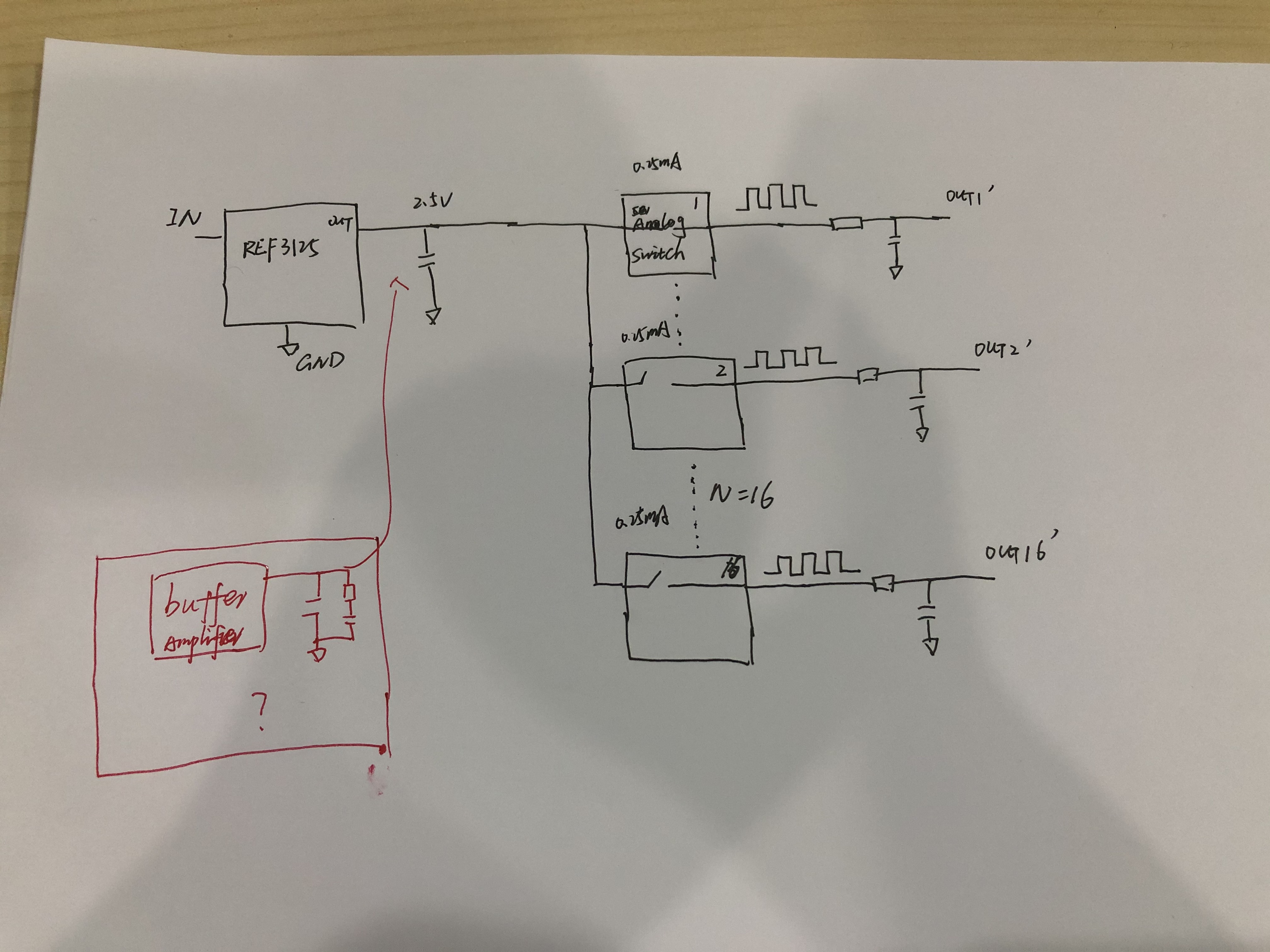
My customer want to use the reference REF3125 to drive 0-5mA (PWM, 4.8khz), Do we have some recommend circuits and amplifier to support the requirement? if we have the simulation results, it should be better. Thanks.

  • Hi Frank,

    can you give some more details?

    Kai

  • Hi Kai,

    Feel free to share what details you want to get. Thanks.

  • Hey Frank, 

    There was quite a lot of composite reference buffer circuit work going on some time back on a few of the SAR ADC demo designs, One such is here where the idea is you get the precision with the front end amplifier and support the sampling current into the SAR reference with the higher speed device giving better settling, 

    I think this showed up in a number of reference designs with different combinations of parts  - the new product folder format does not seem to show those as clearly as it used to. I think the OPA625 also had a number of these, 

  • Hi Frank,

    My customer want to use the reference REF3125 to drive 0-5mA (PWM, 4.8khz). 

    Is this your design requirements?

    Input: 2.5Vdc, 0-5mA or 0.125mW as input power

    Output: 2.5Vp-p, 4.8kHz square wave, how precise do you want in 4.8kHz? 

    Suggested approach, if this is your design requirements: 

    1. Use TLC555 Timer to generate 4.8kHz PWM

    2. 2.5Vref compares with sawtooth input signal, and generate 4.8kHz PWM

    If you are able to provide us the design requirements, we can provide a simulation in Tina. 

    Best,

    Raymond

  • Hi Raymond,

    Thanks for your help. Please kindly check the system below. The customer use REF3125 to generate the 2.5V reference. Then use 16 channel analog switch behind the reference(use 4.8KHZ pwm to control the analog switches on/off. So the waveform behind analog switch is 0v-2.5V PWM waveform with duty cycle based on analog switch control pins. Then use a RC filter to get the output. Currently the max current of every channel is 0.25mA. So the total current of 16 channels are 4 mA. If only 1-4 channels on together, it will not influence too much. But if 16 channels on together, the OUT voltage accuracy will be much worse. Based on current condition, it seems the ref sourcing current may not be enough. We may need to add an additional buffer there. Do you have some suggestions about the buffer solution? Hope we can do a simulation too. Many thanks.  

  • Hi Frank,

    why not taking multiple REF3125, one for each four channels?

    Also, the output decoupling capacitance of REF3125 should be adapted to the needs of PWM circuit. Why not adding a suited output filter to the REF3125?

    Kai

  • Hi Frank,

    According to your diagram, the mux switching circuit will only need approx. 4mA to operate. REF3125 should have enough current to drive this application (should source/sink at least +/-10mA output current as the datasheet indicated.). 

    As Kai pointed out, please try the following circuit first before considering with op amp buffer as Vref approach. Please use low ESR 10uf ceramic capacitors, 1206 or 0805 types. If you need multiple REF3125 ICs, it will be still better options than use a single Op Amp Buffer approach. 

    BTW, if you use multiple REF3125 ICs, each 2.5Vref shall drive several input channels as a group. You can not parallel the output in REF3125 ICs, as Vref output will "fight" among each other.  Please let us know the impedance of analog switches to ground. 

    /cfs-file/__key/communityserver-discussions-components-files/14/REF3125-12102020.TSC

    If you have other questions, please let us know.

    Best,

    Raymond