This thread has been locked.

If you have a related question, please click the "Ask a related question" button in the top right corner. The newly created question will be automatically linked to this question.

Stability analysis and open loop gain measurement of op amp in NIC circuit

Other Parts Discussed in Thread: TINA-TI

Hi,

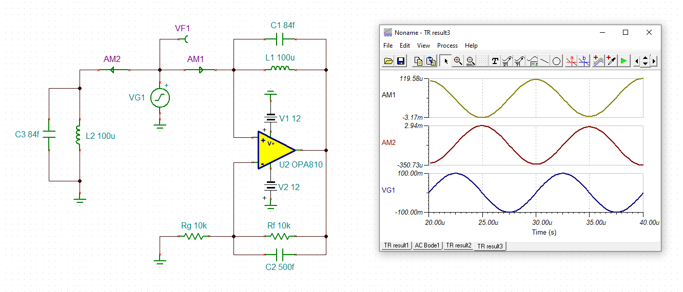
We are designing an 'Negative impedance converter (NIC)' circuit to realize an negative inductance for an EMI filter application.

To achieve the desirable negative inductance two of the methods were proposed in Wikipedia using operational amplifier.

I would like to analyze the stability of the NIC circuit with OP-AMP. I referred all TI Videos & documents related to OP-AMP stability based on Rate of closure technique. It is more helpful.

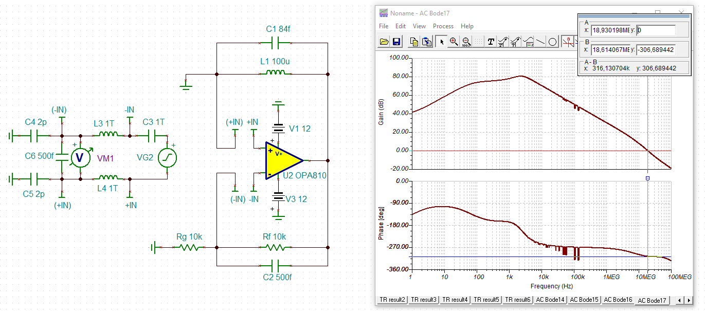
In these stability papers an 1TH inductor and capacitor is added for analysis, but for an NIC circuit the opamp is connected to both negative feedback as well as positive feedback.

Following are the list of calrifications/solutions needed on simulating NIC stabiltiy analysis.

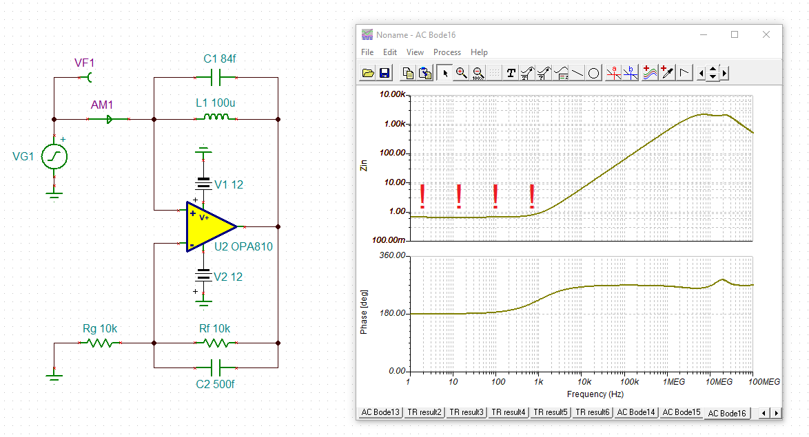
a) I am expecting my op-amp to remain stable till 25MHz, but I hope the presence of inductor will affect the stablity. How to analyze it.

b) Whether It is better to go with an inductor in an OPAMP circuit or an alternate circuit using capacitor which mimic as negative inductance (Please refer Wikipedia for Circuit details)

c) How to make an NIC circuit to remain stable till or above 25MHz.

d) How to measure open loop gain for NIC circuit having both positive and negative feedback circuit

  • Former Member
    0 Former Member

    Hello Ajith,

    For circuits with both positive and negative feedback paths, you will need to apply a different analysis but the general method is the same.  Consider the generic op amp block as with two feedback loops, solve the transfer function, and find the condition in which the closed loop gain is undefined.  I will spoil the surprise and let you know that the critical point is, just like for negative feedback circuits, where Aol * Beta is equal to -1.

    Of course, we'd rather not have you reinvent the wheel.  Please see this post here and scroll down to the bottom.  You'll find a presentation titled, "Dual FB Beta_plus and Beta_minus RevD.pptx".  Download the file and you will find just the calculations showing you how this is derived.  Starting on page 13, you can see the generic circuit to set up to test the stability.  Build this circuit in simulation, place 3 extra capacitors to mimic the input capacitance of the op amp, and run an AC test.  Vfb will give you AolBeta.  So, that's the key signal to get your phase margin.

    This presentation should answer both questions a) and d).  Let me know if you need any help.

    For question b), it looks like the wikipedia page suggests capacitors.  For most smaller applications, inductors are avoided.  I am assuming you mean in real life.  If in simulation, use the inductors to help you test for stability.  For question c), I would use the same techniques as described in TI precision labs.  I can help you with these as well if you decide your circuit is not stable.

    Regards,
    Daniel

  • Hi Ajith,

    please give us a schematic.

    Kai

  •        Circuit showed in figure is negative impedance converter where 'Z' mentioned in figure is inductor

  • Hello Ajith

    The inductor will be problematic because there can be no DC solution. 

    Swap Z with the feedback R1 resistor. Make Z a capacitor.

    Z = -j*2*pi*F*C*R1*R1 per a wikipedia.org formula (I have not verified this)

  • And the proof that it's a negative inductance:

    Kai

  • Hi Daniel,

    Thanks for suggestion, I had gone through the slides it's useful for my analysis, 'Dual feedback stability analysis' referred has the feedback in both inverting and non inverting terminals as ratio of impedance

    Refer NIC circuit below constructed using capacitors and resistors in feedback

    In this circuit the Resistor R1 in positive feedback is acting alone, while R1 and C in negative feedback acts together. In general for AC analysis sources to be grounded hence if input in non inverting to be grounded, R1 in positive feedback will acts as the load. In this case positive feedback don't come in the picture.

    Following are the list of calrifications/solutions needed on simulating NIC stability analysis.

    a) Whether to ground the source acting in the non inverting terminal while calculating open loop gain and (1/beta), where beta is feedback ratio

    b) Input to the non inverting terminal of OP amp will be fed through transformer, How to analyze in this case or how to model the source for Opamp

    Regards,

    Ajith kumar K

  • Hi Ajith,

    how do you want to use this negative inductance at all? What else is connected to it? Can you show a schematic?

    Kai

  • Former Member
    0 Former Member in reply to Ajith Kumar K

    Hello Ajith,

    In the stability setup, you can set your original source to ground or some DC voltage which sets the amplifier in a linear operating region and avoids railing of the output.  The AC test voltage will be provided by the test source.  This is what is done during simulation.

    For the transformer, I would suggest you have a DC voltage, like GND, at the input and the output connected to the rest of your circuit.  If you need help building the model, I would consult this list of google search results from ti.com.  But, there look to be some models available for TINA-TI, if you use that SPICE tool.

    Let me know if you need more help.

    Regards,
    Daniel

  • Hi Daniel,

    Here I'm setting up DC voltages +Vcc and -Vcc for the opamp which sets the amplifier in a linear operating region, what my concern in NIC circuit is Input signal to the non-inverting terminal of opamp 

    In NIC circuit refered in previous post has both feedback (positive and negative). while in negative feedback it has voltage dividing resistive feedback and in positive feedback output of opamp is directly fedback to noninverting terminal (input signal point and positive feedback point) 

    How to realize my circuit in calculation of 1/beta, Consider 2 cases on Small signal AC analysis

    Case 1:  whether to ground the input signal at the noninverting terminal and feeding small signal AC as in single L break method (if doing so my positive feedback path impedance R1 will be acting as a load)

    Case 2: Removing the Input source alone without grounding the input point at Non inverting terminal. In this case we will be having 2 feedbacks, calculating 1/beta by double L or Single L break method 

    Suggest suitable case for my Stability analysis

    Regards,

    Ajith kumar K

  • Hi Ajith,

    again, how do you want to use this "negative inductance"? What else is connected to it?

    Please show a schematic :-)

    Kai

  • Former Member
    0 Former Member in reply to Ajith Kumar K

    Hi Ajith,

    Any time you have dual feedback, you will need to use the double L-break method.  The input signal to the normal circuit will probably need to be replaced with a DC voltage to ensure the amplifier remains in a linear operating region.

    Let me know if you have any further questions.

    Regards,
    Daniel

  • Hi Kai,

    As requested, Please refer the below circuit.

    L5, L6 are the common mode inductor and L7 is the auxiliary winding for sensing the common mode current.

    In General, negative inductance circuit is mostly used for parasitic cancellation and impedance boosting applications.

    In the below circuit, op-amp based negative inductance circuit is used for boosting the common mode inductance. Thereby size & volume of the CM inductor shall be reduced.

    a) The inductor in feedback path will be problematic at low frequencies but the effect of CM noise mostly occur between few KHz to few MHz. In such case whether can i go with this method or i can switch to NIC with capacitor feedback circuit.

    Regards,

    Sadham S.

  • Hi Sadham,

    can you carry out the phase stability analysis using the demonstrated technique by yourself now?

    Kai

  • Former Member
    0 Former Member in reply to SADHAM HUSEN S

    Hello Sadham,

    I believe this question may have been answered by Ron Michallick earlier in this thread.  If you go to the first page, you will see an explanation that he gives there.  Please let me know if that does not answer your question.

    Regards,
    Daniel

  • Former Member
    0 Former Member in reply to SADHAM HUSEN S

    Hello Ajith and Sadham,

    Have all your questions and concerns on this topic been answered?  I hope so.  Please let me know if you have any follow-up.

    Regards,
    Daniel