Part Number: AMC3301EVM
Other Parts Discussed in Thread: AMC3301
Hi
I ordered 3 pcs of AMC3301EVM evaluation boards in 08/2020.
I have found that the outputs of these boards oscillate. The problem is similar in all of these boards.
Here is an oscilloscope screen capture:
AMC3301EVM's INP terminal driven by signal generator with 0Vdc. INN terminal grounded. Power supply's minus terminal grounded.
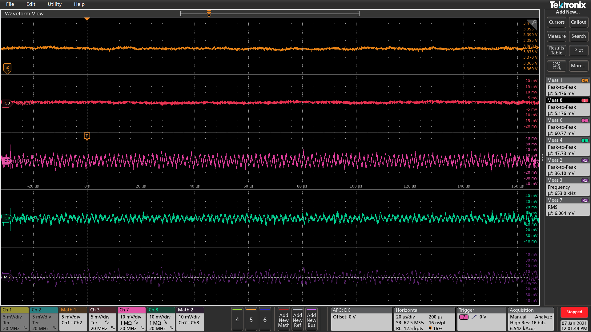
Math 1: VDD - GND (power supply voltage)
Ch 3: Voltage between board INP and INN.
Ch 7: OUTP
Ch 8: OUTN
Math 2: OUTP - OUTN
As it can be seen, the outputs oscillate. There is no excitation at the input nor in power supply voltage at the same frequency.
The situation is similar when the input is shorted. The situation gets worse if the input is open:
Ch 7 frequency measurement "Meas 8" happened to be 1 MHz at the instant this above capture was taken. Most of time it was ~312 kHz.
Here are the package markings of ICs used in these boards:
03AH9ST
PAMC3301Q
G4
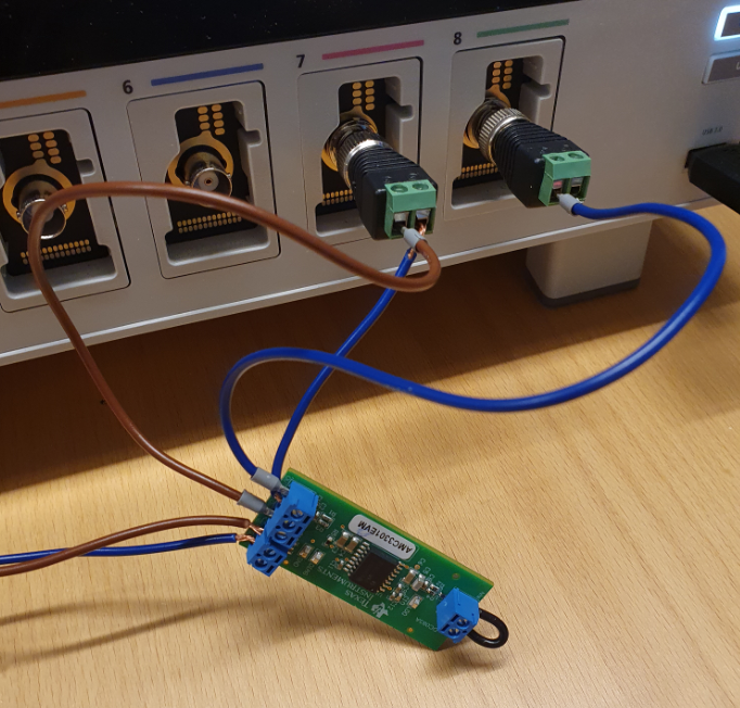
Here is the board used in these measurements:
Is there a design flaw in these ICs or what is going on?