This thread has been locked.

If you have a related question, please click the "Ask a related question" button in the top right corner. The newly created question will be automatically linked to this question.

current measurment switching circuit (high speed)

Other Parts Discussed in Thread: PGA281, TLV3201, OPA846

Hi,

Previously I've made a circuit for uA - A range currents , which seems to work reasonably well (with calibration). 

For high current range the circuit uses 40mOhms resistor with a PGA281 with 32x GAIN. For lower currents the setup is the same just with 10 Ohm.

I'm trying to make a switching circuit , which could switch automatically really fast between the two range with bypassing the 10R resistor with a low Rds FET.

The planned switch threshold would be around 4-8mA . I'm planning to control the switch based on voltage drop on the 40mOhm resistor. However this voltage is around 0.16-0.32mV. I'm afraid that a simple comparator wouldn't work with that low voltages. I'm trying to configure and simulate different opamps to amplify the signal before comparison, but I couldn't find one to perform this task according to my needs. Preferably below 1usec. 

Could you please help selecting the right parts ? 

Regards,

Gabor

  • Hello Gabor,

    Can you please share the diagram of the original switching FET/Rshunt resistor circuit you are working on to ensure to ensure we understand the requirements (or the simulation files you are working on)?  What is the common-mode voltage expected on the Rshunt? 

    I should mention, the PGA281 is a high precision programmable gain instrumentation amplifier optimized for DC performance (relative low BW) that will take time to settle (tens of microseconds).  Is the settling time of the PGA281 a concern? 

    Thank you and Regards,

    Luis

  • Hi Luis,

    Vin would be 12V maximum, but typically 6V. So the max Vcm is around 12V. 

    Of course the BW should be the highest possible, but with 5Khz we should be good. 

    Fast switch is only needed to minimize voltage drop on 10 Ohm resistor. Typically use case is when measuring sleep currents n the MCU wakes up and switch on a display which could consume hundreds mA current .  Goal is to minimize total voltage drop. around 0.2V. 

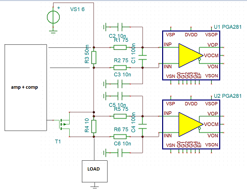
    This is the simplified current test setup. (It's far from final ) . 

    My first thought is to use a differential amplifier with a comparator for switching the FET, and setting the switching point in the overlapping section of the two current range. According to my recent simulation, I think an OPA846 + TLV3201 could do the job. 

    But I'm open minded to any better solution. 

  • Hi Gabor,

    would this scheme do?

    Kai

  • Actually it'd be better to short it with a fet. I'm worried about leakage currents (Idss) which might ruin the uAmpere measurements. it's very hard to find a suitable diode. Also we want to minimize voltage drop. I've tested the setup with a very low Rds FET(2mOhm) . This gives a perfect solution, but need to solve the driving issue. Nevertheless  I've already ordered B0520LW-7-F to check if it could work.

  • Hi Gabor,

    I think error due to leakage current would be acceptable. Here with four 1N5400 in parallel (Onsemi_PSpice_model):

    But total voltage drop at 1A is higher than you would desire:

    gabor_pga281.TSC

    Kai