Other Parts Discussed in Thread: INA250
Hello,
We selected INA253 and INA250 for current measurements in a HIL test rack application.
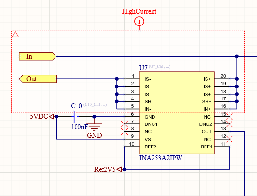
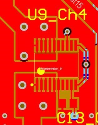
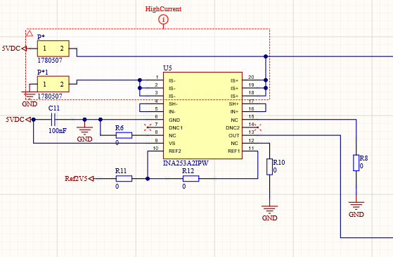
Can I ask you have a look at the schematic and layout below and give a feedback why the old setup did not work and if the new approach should work?
The old approach was like this:
Applying DC currents well in the appropriate ranges (10A) destroyed the sensors. I shorted a power supply directly with the INAs. 12/16 sensors are completely gone: sensor supply current is around 50mA instead of the max quiescent current of 2.4mA in the datasheet. The analog output stays at 0V instead of the reference 2.5V +/-current reading. 4 sensors still look ok in terms of supply current, but the output voltage is off by roughly a factor of two. Seems to be the case for INA253A2 and INA253A3. For example the INA253A2 outputs ~3V when I apply a current of 1A. We identified three areas where the Speedgoat schematic/layouting varies from the TI evaluation board that handles the currents well.
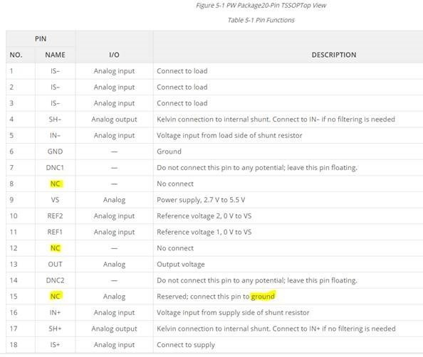
- NC connected to GND:
As a matter of fact, pin 8, 12, and 15 are connected to GND on the eval board.
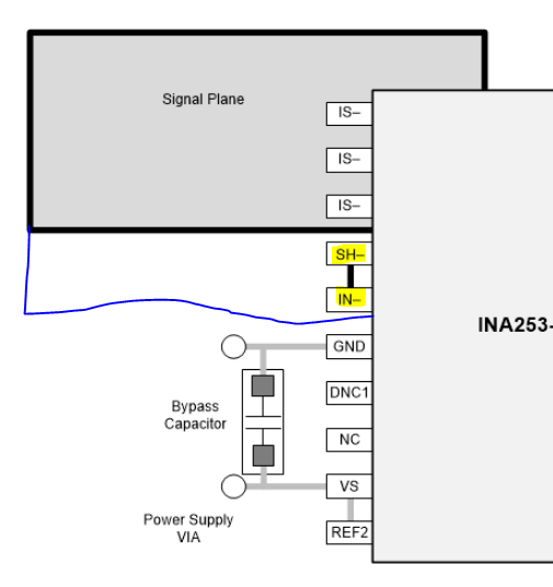
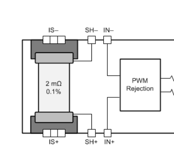
- SH and IN connected to IS:
We layouted a big polygon (signal plane) that includes SH and IN as shown in blue. This is a mistake that might lead to a bigger measurement error, but also doesn’t explain the destruction.
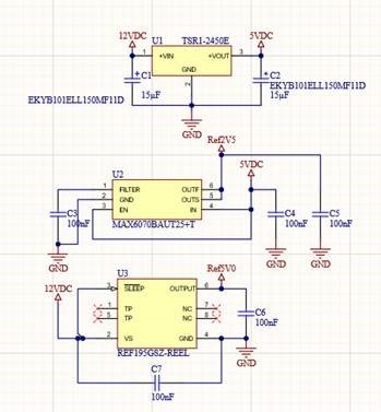
- We used an external 2.5V voltage reference.
The new setup will look like this, the 0Ohm resistors will eventually be replaced by a regular wire :
Thanks in advance for your feedback. Let me know if you would like to know more details.
Regards


