This thread has been locked.

If you have a related question, please click the "Ask a related question" button in the top right corner. The newly created question will be automatically linked to this question.

INA226: INA226 schematic review

Part Number: INA226
Other Parts Discussed in Thread: INA228, INA238

Please help coordinate to see if the following circuit is OK?

The current of the load to be tested is 10ua-500ma. Is it correct to select 3 ohm resistance?

If it is not correct, help to determine the value of the resistance.
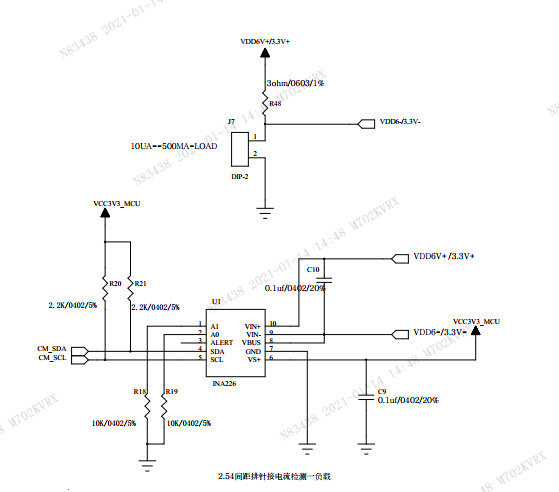
  • Hi Jack,

    hhm, what is the purpose of C10? A drawing mistake?

    Kai

  • Jack,

    I agree with with Kai about the capacitance.  If you need filtering add the 10ohm otherwise the filter will be based on the parasitic resistance.  With the INA226 you will have larger errors at the lower currents.  It has input bias current of 10uA and offset of 10µV.  So at low currents you will have 10µA + 10µV/3Ω = 13.33µA.

    If you would like lower error please look at the INA228 and The INA238.  These input stages would befit from the input capacitance but it does not need as large as 100nF.  Maybe a 1nF capacitor if you use the INA228 and INA238.

    Other than that the schematic looks fine.