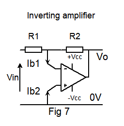
I'm trying to understand how input bias current affects the behaviour of this configuration in relation to a real op amp.
I've read that the inputs should be fed from similar resistances so the effect of input bias current is minimised.
Here is my circuit, I'm using the characteristics of a 741 as my example. R1 = R2 = 10M (yes I know thats large for a 741, just to illustrate my idea.)
and Ibias for a 741 is quoted as 0.08uA
We have resistors R1, R2 of 10M, which gives us a 10M input resistance because the - input is a virtual earth.
The thevenin equiv cct for the resistance seen by the inverting input is 0V / 10M //10M = 0V 5M
The voltage we measure at the output will have an error because Ib1 is fed from a resistance of 5M while Ib2 is fed from a zero resistance.
The error due to the input bias current of 0.08uA is Verror = 0.08uA * 5M = 0.4 volts!
However another view is as follows:
The problem with the simplification is that it ignored how the op-amp will respond when something changes.

The circuit can't be simplified to:
+3v
|
| 10M resistor
|
+----Op Amp -ve input
|
| 10M resistor
|
-3V
Because it will change when something else changes.

The action of the op-amp will be to try to maintain 0V at it's negative input when something else changes. To test what source impedance the -Ve input sees imagine drawing some current from that point. In the circuit above with no feedback the voltage will change according to Ohms law and you can calculate the source impedance from that.

With negative feedback, which is what you actually have, if you draw some current at the mid point then, as long as you remain inside the operating limits of the circuit (supply voltage in particular), the op-amp will adjust it's output to prevent the voltage at its -ve input from changing. If you have voltage source that does not change when you draw varying amounts of current from it then the source impedance of that voltage is zero ohms (or very low).

Sorry, I know this is long but grateful for any clarification.


