This thread has been locked.

If you have a related question, please click the "Ask a related question" button in the top right corner. The newly created question will be automatically linked to this question.

AMC3301: Floating ground and ground reference

Part Number: AMC3301


Hello.

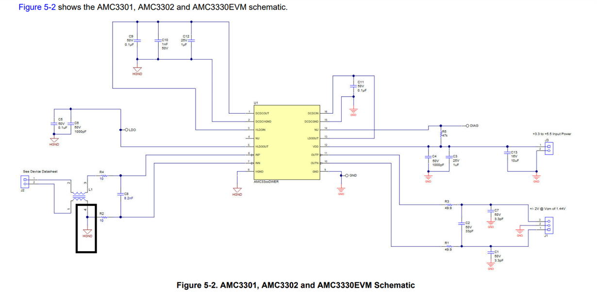
Does the AMC3301 need a floating ground lke the AMC130x family or actually the DC-DC converter does what the transformer and the transformer driver where used to do in the AMC130xEVM?

And, just to clarify, the AMC3031 and it's EVM are referenced the same way, right? I'm asking that because the the AMC130x and AMC130xEVM have some differences about how the GND1 is referenced.

I read this phrase on the AMC3301 datasheet's and it wasn't much clear to me: "For best accuracy, set the ground connection to a separate trace that connects directly to the shunt resistor rather than shorting HGND to INN directly at the input to the device.". Page 26. It says first about the ground and the compares it with a layout shorting HGND and INN. The last statement is very clear about shorting both at the shunt but the ground reference statement before I didn't get it when compared.

Regards,

Vinicius

  • Hi Vinicius,

    Yes the AM33xx family of devices requires a high side ground connection. The internal DC/DC converter does behave in the same way as the transformer and transformer driver for the AMC13xx. The main reason the AMC devices require the high side ground connection is to ensure that the input voltage stays within the common-mode input range of the device. The device HGND floats with the input voltage being measured. 

    The statement is saying that the HGND connection should be routed independently of the VINP and VINN connections to the shunt resistor. This will allow for greater common-mode noise rejection, as well as ensure that the input voltage does not drift outside of the common-mode input range. 

    Remember that the schematic is only a representation of connections, nets, and nodes - not how it is actually routed on the PCB. It is a little difficult to see the routing on the PCB picture in the manual, so I attached a picture here showing the connections. VINP = Yellow, VINN = Blue, HGND = Red. The datasheet doesn't account for the common-mode choke, L1, on the EVM - Hence why the connections are made this way on the EVM. The common-mode choke will not be necessary for your design unless you plan on EMI testing.