This thread has been locked.

If you have a related question, please click the "Ask a related question" button in the top right corner. The newly created question will be automatically linked to this question.

TL082-N: How To Maintain Lifted "Ground" In Single Supply Application w/ Grounded Audio Signal

Part Number: TL082-N
Other Parts Discussed in Thread: TL082,

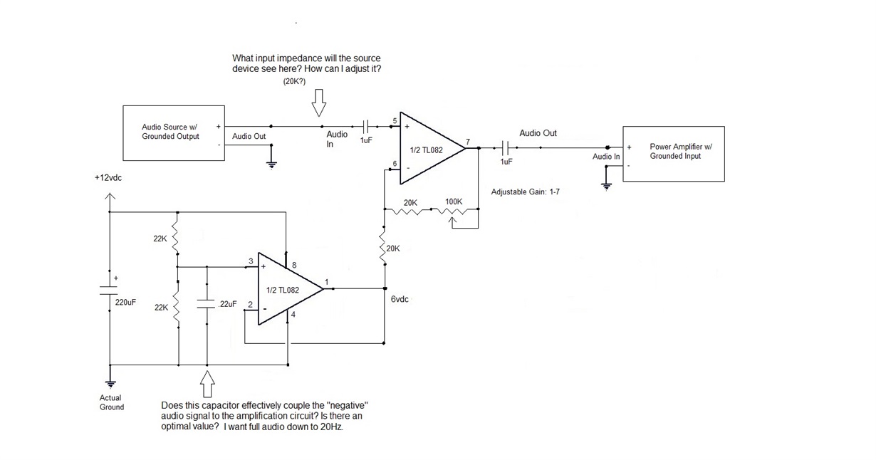
Hello! I am trying to design an adjustable gain audio pre-amp circuit that will be powered by a single source +12vdc for an automotive application. The audio input  and output devices ground the "negative" side of their signal. I'm trying to figure out how to connect these devices to my circuit while preserving the floating ground needed to operate from a single supply. I am using half of the TL082 to establish the elevated floating ground and also AC coupling the real ground through this stage at unity to pass through to the second stage inverting input. I am not getting any output using the circuit shown below. What am I missing to make this work, and are there any other improvements I could make to this for better performance? Thank you!

  • Here are the measured voltages at each pin of the TL082CP. I have no audio currently with this configuration.

    1) 5.96 vdc
    2) 5.96 vdc
    3) 5.90 vdc
    4) 0.00 vdc
    5) 0.201 vdc, .005 vac RMS with audio source muted, .280 vac RMS peaks with source at full output level.
    6) 4.531 vdc, .005 vac RMS with audio source muted, .005 vac RMS with audio source at full output level.
    7) 0.597 vdc, .005 vac RMS with audio source muted, .005 vac RMS with audio source at full output level.
    8) 11.88 vdc

    Pins 1,2,3,4,8 all have .005 vac RMS at all signal levels.

    I have audio signal at pin 5, but nothing out - not sure why.

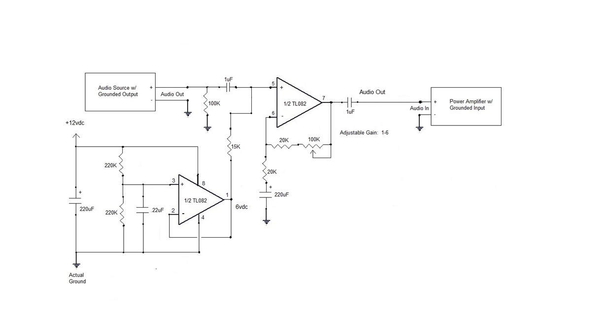
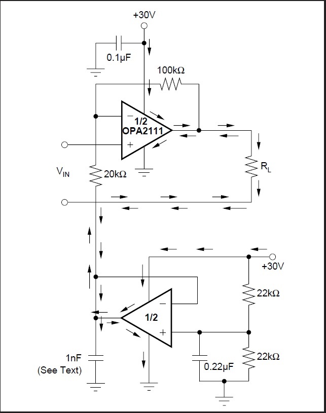
  • After finding more circuit examples online, I was able to resolve my problem by moving the false elevated ground from the inverting input to the non-inverting input. I then coupled the inverting input to (real) ground using a large capacitor.  I don't understand why the other way didn't work. I found an example in a Burr-Brown application bulletin that showed the elevated ground going to the inverting input and both stages were configured as non-inverting just like I did. If anyone can explain why one worked and the other did not I would greatly appreciate the knowledge. Below are the two images of the new circuit that works, and also of the Burr-Brown sample that seems to be a similar configuration to my first attempt. Thanks!

    This works:

    This Burr-Brown example attaches the elevated ground to the inverting input:

  • Former Member
    0 Former Member in reply to Thomas Kuhn1

    Hi Thomas,

    Pin 5 does not have the opportunity to establish a bias point in the first design.  Unsurprisingly, the DC voltage of this pin is near 0V.  When the audio signal comes in, it looks like it's going to try to take the input below GND due to the AC coupling capacitor.  This will be problematic as the amplifier is trying to operate with an input that is below its V- supply voltage.

    It's also important to note that the input common mode voltage range of the amplifier is limited and that the input common-mode needs to be at least 3V above the V- rail.  That makes the TL082-N less than ideal for this design as it is severely limiting the range of voltage that can come into pin 5.  Remember, whatever is seen at pin 5 will be what the op amp attempts to make as its common mode voltage.

    In the second circuit, you provide a DC biasing point that is within the common mode voltage of the amplifier.  This alleviates the situation such that you are now able to get some type of audio signal out.

    Regards,
    Daniel

  • Thank you, Daniel. I think I understand. Why does the Burr-Brown application example work with the floating ground on the inverting input? I guess the key difference is that their source signal is not referenced to ground so it's free to float around  whatever DC bias level the op-amp circuit pulls it to. No decoupling cap is required in that situation. In my situation, the decoupling capacitor would be needed to allow the op-amp to establish it's own DC voltage reference independent from the source and therefore the floating bias needed to be applied to the non-inverting input to establish the reference in a positive direction midway between the rails. Is that about right?

  • Former Member
    0 Former Member in reply to Thomas Kuhn1

    Hi Thomas,

    Yes, you are looking in the right part of the circuit and your explanation seems to be on the right path, though I am not sure I follow it 100%.  Let me explain it as I understand it.

    The two circuits are very similar.  The key difference is how the input arrives.  In your case, the input is capacitively coupled.  So, only the AC portion will get through.  The problem with this is that the common mode voltage of a non-inverting amplifier, like the one on top, is defined by the voltage at the non-inverting input at any given point in time.  With only a capacitor connected to this input pin, the DC biasing voltage is not well-defined.  In your case, you measured that voltage as near 0V.  The problem is that this amplifier cannot take a voltage that is that close to the supply rail because of its input common mode constraints.  So the amplifier does not work properly.  Even if it did, the output would rail to 0V.

    On the other hand, the Burr-Brown circuit has no input capacitor.  So, the input voltage can have a DC bias, such as mid-supply, and ensure that the input of the amplifier is in the proper common mode region.  As drawn here, the input signal goes directly into the input of the op amp.

    Hopefully this somewhat clarifies things.

    Regards,
    Daniel

  • It sure does - thank you. I guess the other distinction in the Burr-Brown example is that the output is a resistive load that is also not decoupled, so therefore it's part of the feedback circuit.

  • Former Member
    0 Former Member in reply to Thomas Kuhn1

    Personally, I think the way the Burr Brown circuit is drawn is a bit more difficult to understand as I find it easier to consider the input voltage and the voltage the load is tied to separately.  The voltage tied to the resistor is not actually connected to the op amp input as there is no current path (see how it is drawn as open).  So, it is not actually part of the feedback loop.  Again, I think it is a bit more challenging to understand as it is drawn.

    In your case, you have an AC coupling capacitor.  Again, this will eliminate the DC bias so you may have problems on the negative swing of the signal as this can dip below 0V.

    Please let me know if anything is unclear.

    Regards,
    Daniel

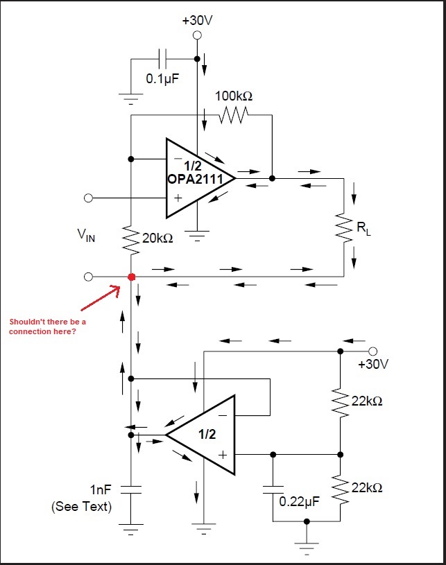
  • I keep thinking about the Burr-Brown example. I may be wrong, but I'm pretty sure it is missing an important connection which I have added to the modified drawing below. Adding this connection is the only way for the current flow arrows to make sense and also to elevate the level of the signal to the floating ground. If correct, you might want to notify the proper people to change the diagram. I obtained this from the "Single-Supply Op-Amps" PDF.

  • Former Member
    0 Former Member in reply to Thomas Kuhn1

    Hi Thomas,

    Hmmm...So I agree that it could be connected in such a manner.  You would simply be tying the load to mid-supply and, assuming there is no issue with the op amp being able to drive the extra current, this seems reasonable to me.

    As far as saying it has to be tied this way...I think it depends on your assumptions.  For example, the current arrows make no sense through the load if there is nothing tied to the load.  In other words, how can there be current through the load if the load is open circuit?  I think the author must have assumed that the node below "Vin" would have been understood to be tied to something.  Otherwise, there would be no point in even having a load.

    As far as elevating the signal level to the floating ground, I'm not sure we are on the same page here.  You can always tie the load to mid-supply from a different buffer.  Additionally, the load could be tied to a different voltage.  Again, I may be mis-understanding your point.  Would you please link to the Burr-Brown circuit?

    Regards,
    Daniel

  • Hi Daniel. Here's the link. I guess I am thinking about these examples always in terms of use with a bipolar source such as audio. I probably am missing something.

    www.ti.com/.../sboa059.pdf

  • Former Member
    0 Former Member in reply to Thomas Kuhn1

    Hi Thomas,

    Thank you for sharing. In the context of the rest of the article, I think I now have a better idea of what is being discussed.

    If you want the load and the input to share the same floating ground, in the same manner as some of the previous circuits in the app note, then I would say it does make sense to tie together the load with the input and the 20k resistor.

    Strictly speaking though, I don't think you have to do this to have a working circuit.  It seems that a significant portion of the article is about getting around the limitations near the voltage rails of some amplifiers.  Obviously, these limitations can be a real issue if your amp is operating in a single supply and the floating ground is one of the ways they would get around this.

    This type of a limitation is less common with newer op amps.  Keep in mind this article was published in 2000 and more rail-to-rail and rail-to-V- parts are available now.  So the necessity for this type of circuit has probably diminished somewhat.

    Regards,
    Daniel

  • We're on the same page now - thank you!

  • Former Member
    0 Former Member in reply to Thomas Kuhn1

    Happy to help.  Please let me know if there is anything else I can do.  For now, I will assume we are good here and will close the thread.

    Have a nice weekend!

    Regards,
    Daniel