Because of the Thanksgiving holiday in the U.S., TI E2E™ design support forum responses may be delayed from November 25 through December 2. Thank you for your patience.

This thread has been locked.

If you have a related question, please click the "Ask a related question" button in the top right corner. The newly created question will be automatically linked to this question.

TLV4113: SHDN Enable ramp has 200µs of leading oscillation

Part Number: TLV4113
Other Parts Discussed in Thread: TLV4111, TLV4110

When driving a 10 Ohm resistor on the output of the TLV4113 with a 1V output for 100 mA current. The input of the OpAmp was stable while the SHDN# was pulled high.

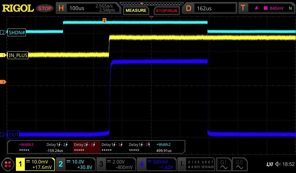
We note about 200µs of leading oscillation before the output stabilizes. At lower voltages, the oscillation is weaker, but there's still a 200µs period before stabilizing. 

  • Hi Lawrence,

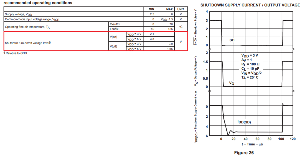
    Can you share the schematic with us? Here is the shutdown pin requirements. 

    Best,

    Raymond

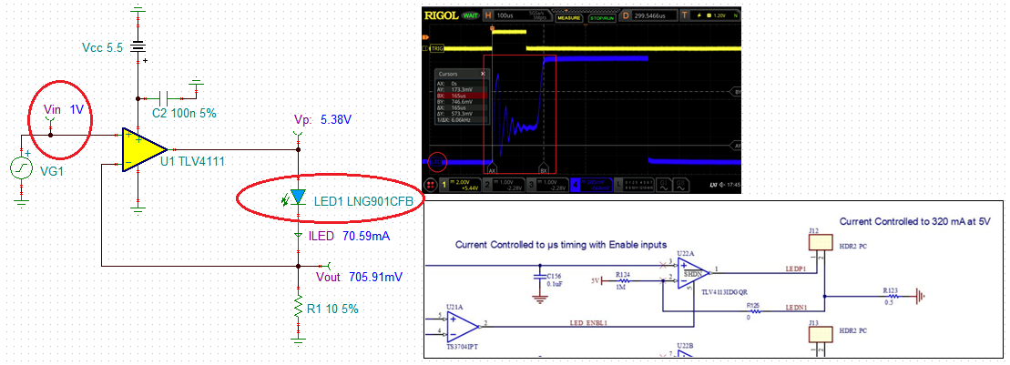
  • Here is our schematic. We have verified that the shutdown pin is cycling to the rail at 0 and 5.4V. Although the schematic says 5V, we increased the '5V' supply to 5.4V to allow more headroom for driving blue LEDs. 

  • Hi Lawrence,

    Q: When driving a 10 Ohm resistor on the output of the TLV4113 with a 1V output for 100 mA current. The input of the OpAmp was stable while the SHDN# was pulled high.

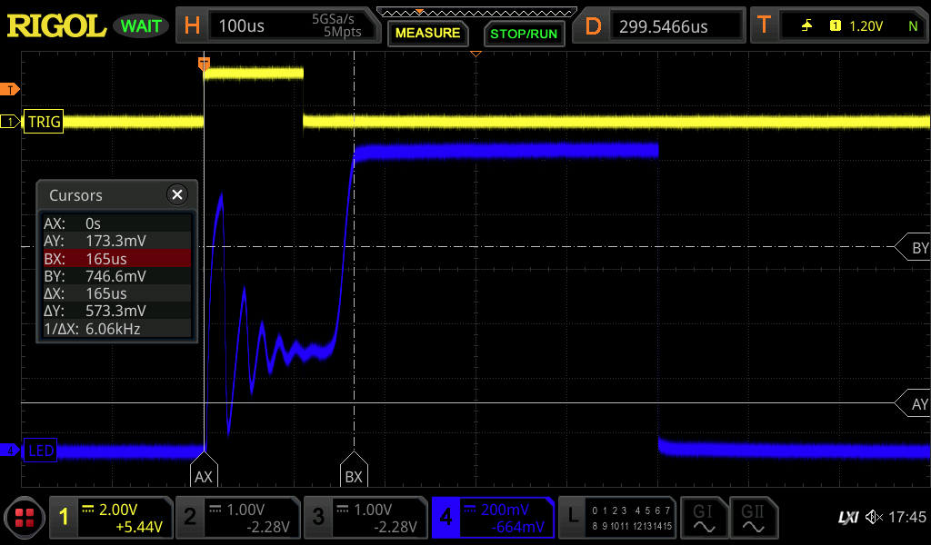
    I would like to understand your LED driving schematic. You are driving LED with up to 320mA of current at 5V. This is voltage to constant current driving circuit. The circuit LED in your screen shot is LED waveform at the output as shown in the image below.  SHDN pin pulled high means that the op amp's output is On. You may observe an oscillation when you measured voltage at the blue LED's output at 1V?

    Can you provide me the blue LED's PSpice model used in the circuit? As it is right now, I am not sure that TLV4113 is operating in linear mode. It seems to be operating in comparator mode. 

    Please provide me with the voltage and constant current levels that you want to drive the LEDs. If you are using TLV4113 (op amp) as comparator, then it does not require the feedback (just require a reference voltage at V-), and you are unable to control the current level through the LED (brightness of LED).  So I would like to know what are the connection at J12-J15 connectors, and I can check out stability of the circuit. 

    Best,

    Raymond


  • Hi Raymond,

       Our intent is indeed to drive LEDs of different colors. However we found the same effect in driving simple resistors. In the scope trace above we were driving a simple 10 Ohm resistor at 100 mA, for 1V output. We see nearly the same effect for different resistors and LEDs. So if we can solve this problem for the resistor, we suspect it will go well toward being solved for the LED. The output connectors go directly to the single component driven, an LED or resistor. So please try putting a generic 10 Ohm resistor into your PSpice model on the output connector J12-J15. 

    We wish to drive in current mode to adjust the brightness of the LED, and turn on the LED in 0.1 msec for short pulses. We do want current feedback as LEDs are diodes with exponential dependence on voltage, so the current is not stable. 

    I note you use a larger 10 Ohm resistor in your example circuit. Since we wish to generate short pulses in the 300-500 mA range, that would not leave any voltage header for the LED, which takes 3-4V across the diode itself. 

    Thank you for your help, 
    Larry

  • Hi Larry,

    Q: We see nearly the same effect for different resistors and LEDs. 

    You are using the TLV4113 op amp as comparator in the test condition. Therefore, the output amp's output is always close to 5.5V ( or rail voltage), which means you will not see the current changes at the LED or brightness changes at the LED. 

    If you use less than 1V (0.1V to 0.7V or so) and remove 1MOhm/5V resisitor (as shown in my simulation), then you may operating at linear mode (only conditionally). If  the input voltage goes above 0.7V, the circuit may go back to comparator mode. 

    Q: I note you use a larger 10 Ohm resistor in your example circuit. Since we wish to generate short pulses in the 300-500 mA range, that would not leave any voltage header for the LED, which takes 3-4V across the diode itself. 

    What is voltage drop across the LED when it is on (I need to know if order to simulate the circuit)? You can give me a part number, if you like. With the current circuit, TLV4113 may not be able to source 500mA and regulate the current at the same time, but I can try it and provide you with a simulation or recommendation. 

    Best,

    Raymond 


  • We see very good current control on the output all the way from 0 to 300 mA. In particular, on the 10 Ohm resistor we requested 100 mA and indeed see 1V on the scope trace for the output that was attached above. 

    The 1M resistor to 5V  is superfluous, has no effect, and will be removed in future layout. The 0.5 Ohm resistor to ground highly dominates over the 1M resistor. 

    Different color LEDs have different diode voltages from 2 to 4V, depending on color. Blue is a higher voltage. But this is irrelevant. We see the same effect with a single resistor, no diode on the output. Please model with just a resistor on the OpAmp output. We see the same issue with a simple resistor. What is going on? 

  • Hi Larry,

    Different color LEDs have different diode voltages from 0.2 to 0.4V, depending on color. Blue is a higher voltage. But this is irrelevant. We see the same effect with a single resistor, no diode on the output. Please model with just a resistor on the OpAmp output. We see the same issue with a simple resistor. What is going on? 

    1. Red LED's forward voltage is approx. 1.7 to 2.0V, Green's FW voltage is approx. 2V and blue's FW voltage is approx. 3V to 3.3V 

     2. Human eyes do not perceive red, green and blue color equally. The eye retina color response looks like a bell curve; most sensitive in green color, red and blue are the least sensitive. Therefore, you have to drive constant current differently for different LED colors (if you want to perceive the color with the same intensity).

    For blue LED, say Vfw=3.3V, op amp's ouptut is only 5.5V per the configuration. the blue LED will have voltage drop approx. 5.5-3.3=2.2V. In order to source 300mA, you will need 2.2V/0.3A=0.67 Ohm sensing resistor for blue LED. 

    In addition, you may have oscillation or Op Amp instability issues with LED as load (capacitance in LED as load). We need to find a way to compensate it, if it is an issue. That is the reason that I have to model the actual LED in simulation.  

    Best,

    Raymond


  • I'm sorry in that I meant the diode drop is from 2V to 4V. I inadvertently added a decimal as I was being distracted at the time. And we sometimes go deeper blue with higher voltage plus the LED has some additional series resistance. So we sometimes see nearly 4V across the LED. But again that's NOT the issue with our oscillations, which occur for a simple single resistor and no LED or diode on the output. 

    We're well aware of the color mapping of the eye. But these colors are needed for particular testing purposes and are sensed with photodetectors using ratios for calibration. So the human perception is not relevant to our need, or the issue at hand.

    We see the oscillation WITHOUT an LED. We see the oscillation with a single RESISTOR on the output and no LED. Discussing and modeling the LED is not relevant until we understand why the oscillations occur with a simple resistor on the output of the OpAmp. We see this highly repeatable and on several boards and for most all currents. At lower currents there's less oscillations but in all cases it still takes about 200 µs after SHDN# goes high before the output suddenly stabilizes and behaves as expected from then on. 

  • Hi Larry,

    I did what you suggested with a single Resistor at the output (no LED), TLV4111/TLV4113 op amp should not oscillate. It will handle 10kHz input switching signal. 

    /cfs-file/__key/communityserver-discussions-components-files/14/TLV4111-E2E-02032021.TSC

    In the model, I am unable to simulate the SHDN# pin Off/On as you had in the screen shot. There is t(ON) time on period and you need to turn on the amplifier first, wait several usec or longer, then apply the input signal. In other words, I do not see oscillation as shown in the screen shot. 

    Please make sure that the TLV4113 needs to be operated in linear mode, where V+ = V- at the op amp. If one voltage is greater than other pins or vice versa, you are not running in an op amp linear mode. 

    Best,

    Raymond 

  • Raymond,

    Your model shows you are using the TLV4111. This model does not have the SHDN# pin. You need to be using the TLV4110 to model the single OpAmp with the SHDN# pin. 

    Furthermore, we were able to see rapid transitions on the OpAmp output in several µs upon a step rise of Vin from of the D/A. Our problem with 200 µs delays and ringing occurs when the D/A output voltage is constant, but the SHDN# pin is enabled. Please model this behavior with the proper device.

    Thanks,
    Larry

  • Hi Larry,

    TLV411x has the same model and die as the datasheet indicated. The Green-Williams-Lis PSpice model does not simulate the Shutdown pins. 

    Let us rule out shutdown pin issues. Please pull the shutdown pin high and feed your D/A signal, and send me the screen shot. 

    Best,

    Raymond

  • Hi Lawrence,

    Let me jump in a bit and see if I can help.  I'm not going to focus on the model at all, as these are macromodels (not transistor level models) and don't model the subtle nuances of a device going in and out of shutdown and such.  They're generally functional behaviors modeled.  

    Help me a understand a bit here.  The TLV4113 has a low true (/SHDN) pin.  In your original scope shot, it appears you have the [yellow] shutdown pin low and then pulse it high (active) for maybe 110us or so, before bringing it back low (shutdown).  Are you expecting the output to stabilize all in that time?  I do see that the datasheet figure 24 does show a short duration disable of that timeframe, but not such a short duration enable.  I can say that most customers don't use shutdown pins to provide output pulses; they would typically pulse the DAC and rely on the bandwidth/SR of the amplifier, not on the on/off/settling times of a shutdown function mostly meant to provide a power saving state.    

    When in shutdown, the two inputs are pulled completely apart (aka in "comparator mode" as others said previously) since the DAC forces In+ to 1V while the output load to ground pulls In- to ground.  When coming out of disable, there will be ~1V differential across the inputs and then feedback works to bring them back together.  My first natural reaction is the non-linear impedance of the diode causes some ringing.  But you say you've tried this with a resistor instead of a diode as well.  I see a 2-pin connector... did you place that resistor remotely on the other end of a cable, or as close to to the Vout/In- nodes as practical?  If there is cabling (or even long traces/connector) present of course my mind goes to L*di/dt where the current went from zero to 100mA in no time at all while the op-amp is still running open loop.  

    A picture or two of your setup might be helpful.  

    Thanks,
    Scott

  • We're getting you a cleaner picture. The TRIG is not the /SHDN line, but something else. Also, the initial plot above showing ringing is with a Resistor, not an LED or diode. 

    We are indeed trying to make ~200 µs pulses of using the /SHDN line, Figure 26 from the data sheet, also given in the second post by Raymond, shows the output going high in a few µs, which is what gave us hope that gating with the /SHDN might work. 

    We're now generating an identical scope trace to the original, driving into a 10 Ohm resistor with les than a 10" lead, but driven by the rapid rise time of the DAC. We know this is fast (a few µs) without ringing and are getting you the trace. This implies it's not a circuit issue. But doing the other way around, constant DAC output on In+ with /SHDN gating of a several milliseconds gives 200 µs of ringing before settling down as per the original post.

    Thanks for your help. 

  • Thanks Lawrence.  For an "inside the op-amp" point of view, there can be a big difference between the two scenarios

    - When you're pulsing with the DAC, all the op-amp internal biases are settled, the fast op-amp sees much of this as small signal transients (depending on input speed/magnitude of course, which a zoomed in scope plot can potentially help).  The inductance of the cable and resulting L*di/dt is still there but the op-amp is in "a happy place." 

    - When you're pulsing with the /shutdown pin, possibly none of the op-amp internal biases are in a good place, it's not a fast op-amp but rather acting as a comparator in potentially slew limit, etc.  The inductance of the cable and resulting L*di/dt eventually get compensated for once the op-amp is in a "happy place", but that might take some time.  

    I think it would behoove you to see if you can mimic the datasheet plot's rapid enable with a purely resistive load in a pretty tight area (no cable, long blue wires, etc).  Note for a couple MHz amplifier in unity gain, 10" can feel like a mile.  And of course then there is how does the AC return current flow.  Safe to assume the two wires are physically adjacent, or twisted, and not forming a nice big loop on the lab table?  

    Thanks,
    Scott

  • Scott, the cable is indeed slightly twisted together between outgoing and incoming current to the connector. We can try putting a resistor right on the connector to be sure. 

    I just measured on the board, and the output of the OpAmp to the connector is a 7.6 mm long trace. The return is a 3.6 mm trace adjacent to the outgoing, but has other lines going to the sense resistor, total to 9.3 mm of traces altogether. 

    Looking more at Figure 26, it shows the output rising with /SHDN as being very fast (microseconds) without ringing. Fig 26 is using a 1.5V output instead of our 1.0V, and a 100 Ohm resistor instead of our 10 Ohm. We can try that configuration. 

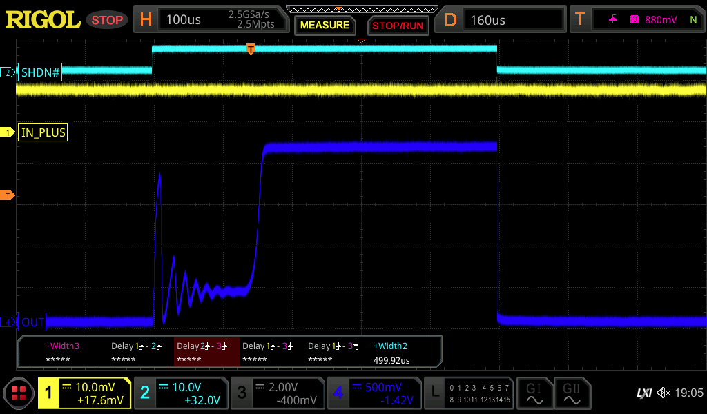
  • We took some more scope traces that are more clear. Each of them looks at the output of 2V on a 10 Ohm resistor. 

    Note that the IN+ probe is reading 10X too low, so the actual input on IN+ is 100 mV/div, not 10 mV/div. 

    The first trace shows ringing when gating with the SHDN# line, while the IN+ is held constant. 

    The second trace shows no ringing when the SHDN# is held high, and IN+ signal is gated by the DAC output. 

  • In the data sheet Fig 26 the test circuit appears to be configured for unity gain.

    We have a gain around 20X in our configuration. Maybe that's an issue? 

  • Lawrence, in the schematic you shared previously, the op-amps appear to be in unity gain.  What am I missing?  Where is this 20X gain?  Thanks.  

  • The OpAmp is designed for constant current control using a 0.5 Ohm resistor. The total voltage gain required depends on the load resistor. For a 10 Ohm load resistor, the voltage output required is 20X higher than the 0.5 Ohm sense resistor in series.
    For the above traces, driving on a 10 Ohm resistor with 2V, the current is 200 mA, with 100 mV across the 0.5 Ohm sense resistor, same as the IN+ and IN- input voltages. 

    For an LED, the current will be a bit lower for a given output voltage, with a bit lower sense voltage. So the gain will be a little higher. Nevertheless we see a similar response with a resistor and LED. 

  • Hi Lawrence, 

    I sort of see what you're saying.  But the op-amp closed loop gain is not dependent on your input-V to output-I transfer function.  The op-amp only sees voltage in terms of feedback. 

    - So let's say your LED diode theoretically has a 2V forward drop during conduction at 100mA, and 2.2V at 200mA. 

    - If you use a 10ohm "load" resistor your DAC forces 1V and 2V, respectively. 

    - For 100mA, the output would be at 1V+2V=3V.  The non-inverting (noise) gain is therefore 3V/1V=3V/V.  

    - For 200mA, the output would be at 2V+2.2V=4.4V.  The non-inverting (noise) gain is therefore 4.4V/2V=2.2V/V.  

    - If now you instead use a 0.5ohm "load" resistor, your DAC forces 50mV and 100mV, respectively.  

    - For 100mA, the output would be at 50mV+2V=2.050V.  The non-inverting (noise) gain is therefore 2.050V/50mV=41V/V.  

    - For 200mA, the output would be at 100mV+2.2V=2.300V.  The non-inverting (noise) gain is therefore 2.300V/100mV=23V/V.  

    So I think we're saying the same thing here, that the effective gain changes with different "load" resistors, but maybe saying it in a different way.  Now as to whether that could make a difference... absolutely it might.  Of course the closed loop bandwidth is different in a gain of 41V/V vs 3V/V.  But as you said, it occurs even with a resistor in a notably lower gain, albeit not a gain of 1V/V like the datasheet shows.  So I encourage you to reproduce the datasheet plot in unity gain with no added inductance and then go from there (changing gain, adding cabling, adding non-linear diode, etc).  

    Note I use "load" in parenthesis as the load is really the whole feedback network including the diode.