This thread has been locked.

If you have a related question, please click the "Ask a related question" button in the top right corner. The newly created question will be automatically linked to this question.

OPA832: TINA-TI SIMULATION ISSUE

Part Number: OPA832
Other Parts Discussed in Thread: TINA-TI, BUF602,

Hi sir,

Mu customer have tried to simulate a very simple circuit (Figure 7) following a database of OPA 832 in TINA-TI,

however, with only positive single supply (+5 V) I could only observe half wave signal (input: 3V, 1Hz),

however applying dual supply of (+- 5V) gives full ac output. Can anyone help me to clear up! Thanks in advance.

Circuit file attached.

SimulationDesign.TSC

Could you pls give me the logical explanation on why it is not operating in the negative half cycle for positive supply only.

If that the case, is it possible to use this circuit as a half wave rectifier?
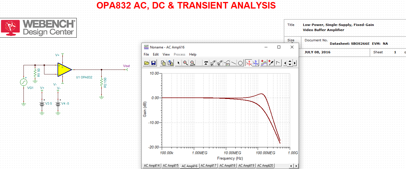
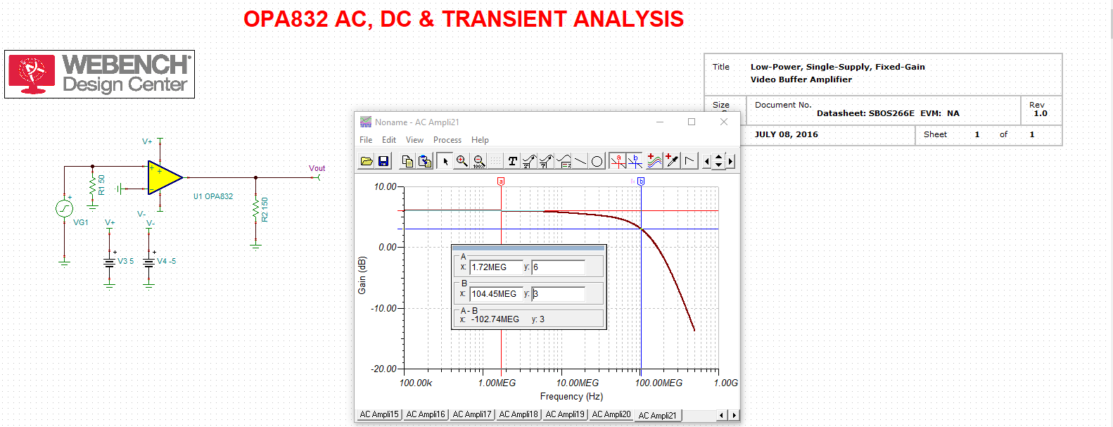
Furthermore, with increasing the input voltage (5V, 13.56MHz),

why I can not get the unity gain but works fine with 3V and modifying the circuit is not resulting double gain.
Any suggestions please!

  • Hi Frank,

    this circuit contains a drawing mistake. It cannot work with a bipolar input voltage because when becoming negative the input voltage leaves the common input voltage range of +0.1...+3.0V.

    As a remedy either you use a bipolar supply voltage of +/-5V, e.g. or use an input biasing scheme similar to figure 1.

    Kai

  • Hello Frank,

    In addition to Kai's comments, even if the amp was following the typical common-mode input voltage range of -0.5V, the output range doesn't go below ground.

    Best,

    Hasan Babiker

  • Hi Kai, Hasan,

    As you mentioned, customer tried to simulate Figure 1 in the datasheet but still the gain is not +2.
    BTW he is looking for single-supply buffer circuit, 

    do you have any other Opamp model suggestions that can operate for a single supply of <= 5V?

    Thanks a lot.

  • Hhm, works for me, Frank:

    frank_opa832.TSC

    Kai

  • And without input voltage divider:

    Kai

  • I was also interested in the "improved" buffer comment - I was doing all this back in 2003, but forgot this little trick - here is a comparison from simple gain of 1 and then the improved version shown in figure 7

    These bandwidths in the model are quite a lot higher than in figure 8 of the datasheet which was almost certainly measured. 

    If I do just a simple gain of 2 grounding the - pin, we get quite a bit higher -3dB than the datasheet reports - It is looking like the model is way too fast vs the part, going into the netlist, it was updated in 2016 to a macromodel - the original model was probably transistor based and much closer than this - if I can get V11 working again, that model is probably in the library. 

    As for alternate single 5V buffers, would need a lot more information if you want DC coupled. If not, look at the BUF602 which includes a midscale set up and buffer internally. 

  • Incidentally, I did get my V11 working again and the library model for the OPA832 is the same 2016 one on the product folder - somewhere out there the original transistor level model (probably by Rea Schmid) might give more accurate AC results. 

  • Hi

    Thank you for your reply but when I checked your circuit I noticed that you modeled it for dual supply but not for a single supply which is my requirement.
    is there any comments?

    Thanks a lot.

  • Hey Frank, 

    I was just checking Figure 7 in the data sheet, which I see now was single supply DC coupled - that was a mistake, should have been +/-5V

    Kai has pointed out that if you use single supply you will run into I/O clipping issues that you need to consider. 

    Again, for gain of 1

    1. Do you need to be DC coupled - if so, what min max input voltage and speed

    2. If you can be AC coupled, Kai has shown some working examples single supply where the blocking caps center up the swing on the supply. 

    3. If you can be AC coupled, that is what the BUF602 was designed for.