This thread has been locked.

If you have a related question, please click the "Ask a related question" button in the top right corner. The newly created question will be automatically linked to this question.

TI LT1013 op amp does not follow the input

Other Parts Discussed in Thread: LT1013

 I'm using a TI LT1013 op-amp to process the current through a 50 mV shunt. I'm having some issues with the op-amp not performing well in certain conditions and I'm not sure why.

It seems that the output of the opamp does not follow the input although the inputs are with Common mode range and the outputs should be well within the rails. The issue happens mostly at higher current values. Any ideas on why it is not operating correctly?

 I attached the schematic section I use.

5280.crt_sense.pdf

  • Matt,

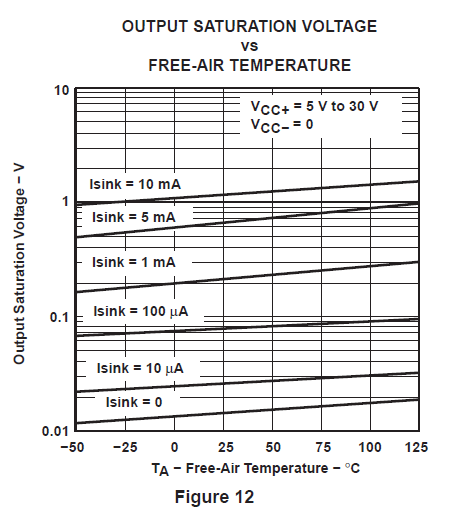
    The output of an op amp typically does not follow the input because the output is over-driven beyond its linear range.   LT1013 output swing, especially close to the negative rail, is a strong function of the output current and may be as small as 15mV from negative rail with no sinking output current (see below)


    or as high as typical 1V  (maximum 2.5V) from the either rail with just few mA of the output current at 25C (see below).


    Short of knowing your exact circuit conditions, I am not able tell you what causes the problem you see but please take a closer look at the graph below showing the Output  Saturation Voltage as a function of ambient temperature for various sinking current levels.  You seem to use single supply (0V to 15V) with 10k||150k load resistors and depending on their exact connections these may result in various output current levels.


    Keep in mind that since the LT1013 uses a bipolar process (see schematic below), the output non-linearity will begin long before the output is fully saturated; thus you need to give yourself a voltage margin at the output if you do not want to see any non-linearity - for this reason, you should use the min and max output swing of 2.5V to either rail instead of typical values.


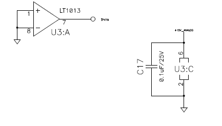
    Also, do not short the inputs in unused channels (see below) - this causes the output to be completely saturated against one of the rails and may effect the linearity of other channels.  Instead, place the unused channels in a buffer configuration with the positive input well within the rails.