This thread has been locked.

If you have a related question, please click the "Ask a related question" button in the top right corner. The newly created question will be automatically linked to this question.

OPA735: Is it possible to make a 3A current source?

Part Number: OPA735
Other Parts Discussed in Thread: OPA548, OPA192, OPA541, OPA549

Hi team,

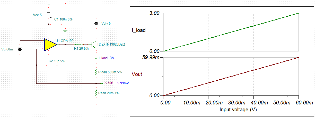
I saw a TI design about 500mA output which is "1% Error, 0-5 V Input, 0-500 mA Output, Low-Side Voltage to-Current (V-I) Converter".

May I know that could it achieve 3A output current?

If yes, how should I modify it?

Thank you.

Best Regards,

Cindy

  • well Cindy, anything is possible - just need to use power transistors. 

    Would help to know what your load looks like, supplies available, any speed or DC accuracy targets

    The TI-designs you attached has the load actually floating with a sense resistor below that - is that ok?

  • Hi Cindy,

    The current source circuit you reference from the applications note can be applied to a higher current application, but as MIchael mentioned the load must be floating. Generally, for high current applications where the current is in the amperes I most often apply the Improved Howland Current Pump (IHCP). Instead of adding external power transistors to a low power op amp's output, a power op amp such as the OPA548 can be employed directly. It is capable of delivering up to 5 amperes of output current. An advantage that the IHCP offers is the output load can be connected directly to ground should that be an applications requirement.

    Here are some TI documents I think would be helpful:

    https://www.ti.com/lit/an/snoa474a/snoa474a.pdf

    https://www.ti.com/lit/ds/symlink/opa548.pdf

    The current source accuracy, be it the circuit you reference, or the IHCP is dependent on the dc precision of the op amp and the precision of the resistors used to establish the current output. Since the current source you need has to deliver 3 amperes output the circuit will be dissipating a fair amount of power and there will be substantial heat generated. The circuit heating and the components affected by that heat need to be considered when establishing accuracy.

    We do need to know the circuit parameters that MIchael mentions in order to better assess what is needed to best satisfy the application. 

    Regards, Thomas

    Precision Amplifiers Applications Engineering

  • The Howland is a good choice up to a point, 

    it needs really good resistor accuracy to operate well, and at higher currents there will be a tempco issue on that, 

    I did find find a +/-5A bipolar >1MHz design (into a grounded load) I was doing for ON semi some time back using these power transistors, if you head that way, 

    PNP, NSS60100

    NPN, NSS60101

  • Hi Cindy,

    I see Michael and Thom are providing good suggestions. 

    Since we do not know your load, BW and other performance requirements, I simulated an example below. It will work as a constant 3A current source at 5Vdc. 

    /cfs-file/__key/communityserver-discussions-components-files/14/OPA192-5V-3A-Drivers-02182021.TSC

    Best,

    Raymond

  • Hey Raymond, I always wondered on this simple approach what the load thinks the source impedance is? 

    good current source would be very high, the Howland is with ideal R values. 

  • Hi Michael,

    I think that this is a voltage controlled circuit, and it behaves like LDO. Vout at Rsen follows the input Vg and keep Vout constant. The current through R_load is independent of Vg, and I_load is constant because Rsen is a constant. So the R_load should see low impedance when it looks back at T2, R1 and the output of OPA192. 

    Best,

    Raymond

  • Also Cindy, if you need TINA models for these transistors, I had at the time imported them. They are only 1A devices, but I chose them since I needed a faster devices for a target 1MHz current source. There are of course higher current slower devices that might be better for your app. 

    ON power transistors.TSC

  • Hi Michael, Thomas, Raymond,

    Thank you all for kindly providing your professional insights.

    Customer hopes to make a current source of 3A continuous and 6A peak with input voltage from 24V to 48V.

    Their application is driving a 40mH induction coil to control motor rotation. 

    We're now thinking to use OPA541 to achieve this function.

    However, we don't know how to calculate the Is, current of power rail.

    Could you please help to advice how much current will it need in their application?

    Thank you.

    Best Regards,

    CIndy

  • Hi Cindy,

    Okay, the application does open additional questions that I am sure Michael, Raymond and I will have. The OPA541 and OPA549 are the two TI power op amps that can operate in this higher voltage range and supply 6 Amperes of output current. They have some different specifications and features so one may be a better choice than the other for this particular current source application.

    Remember a constant current source sources a constant current, and unless the input control voltage is changed the current remains the same. If I understand the current source requirements correctly, the input voltage to the power op amp will be 24 V for a 3 ampere output, and 48 V for a 6 ampere output current? Do understand that the supply voltage will need to be several volts above the common-mode voltage (Vcm) applied at the input for linear operation.The maximum positive VCM for these two power op amps is about 3 V below the positive supply rail. Therefore, realistically the positive supply voltage Vcc, should be no lower than about +52 V. I would suggest it being a few volts higher.

    You mention the 40 mH induction coil. Certainly, there is some coil resistance as well and that needs to be understood. If the coil is purely inductive the output voltage and current are split by 90 degrees and the op amp power dissipation becomes more complex than when driving a resistive load. Even with an complex R + jX load the voltage and current will still be split and the power dissipation must be fully understood.

    So a bit more information is needed before a practical design can be developed.

    Regards, Thomas

    Precision Amplifiers Applications Engineering