This thread has been locked.

If you have a related question, please click the "Ask a related question" button in the top right corner. The newly created question will be automatically linked to this question.

INA213: IN+ and IN- connection

Part Number: INA213
Other Parts Discussed in Thread: TPS62130

Hi team,

in the INA213A datasheet, the IN+ is connect the supply side,  IN- is connect to load side.

but in the A/N of SLVA657, the IN+ connec to load side while the IN+ connect to supply.

can you help clarify which one is correct?

  • Hi Betty,

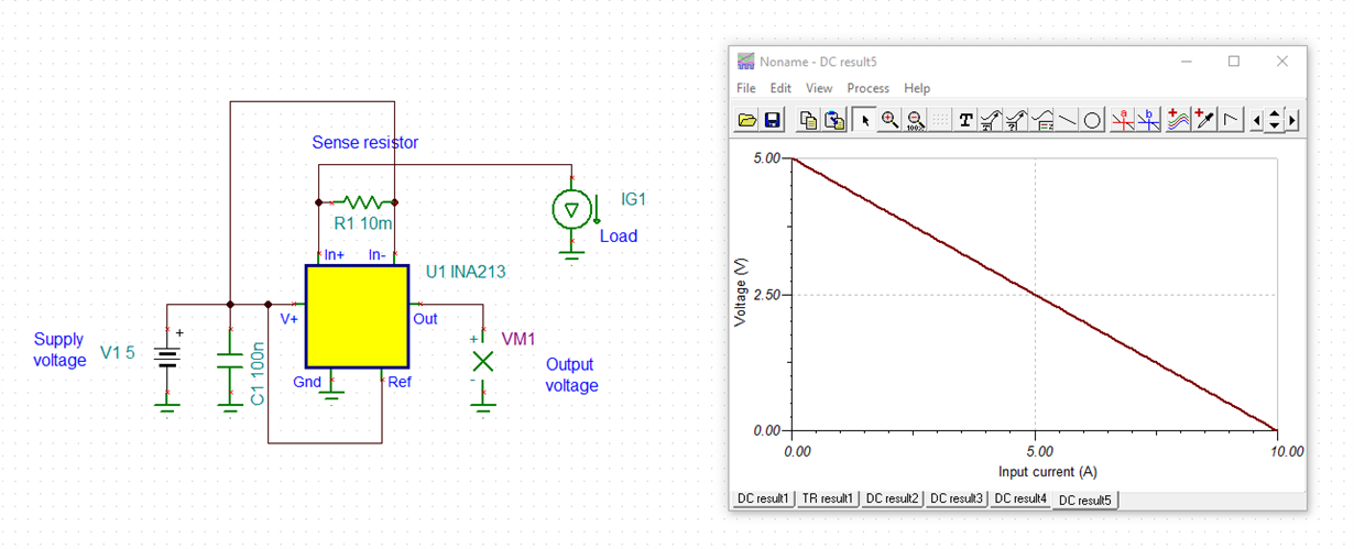
    like this?

    betty_ina213.TSC

    Kai

  • Betty,

    Kai has provided a great visualization here of how the INA213 behaves in in SLVA657.

    The answer is both are correct design implementations, but most likely for your application, you will want to stick to the datasheet for your design.

    Regarding SLVA657, note that the REF pin is set to VOUT0, so that at light load ~0 condition, the output will be ~VOUT0, and as the load current is measured in this direction, this output voltage drops rather than grows. This inverse behavior is needed in the design due to their feedback control scheme, as the output of the INA213 is controlling the FB node of the TPS62130.