This thread has been locked.

If you have a related question, please click the "Ask a related question" button in the top right corner. The newly created question will be automatically linked to this question.

XTR111: No output current while EF can sense open loop.

Part Number: XTR111


Trying to implement xtr111-2evm reference design in my project can't make it work. Input is DAC 0..2V, Rset is 1k. According to datasheet output current should vary from 0 to 20mA. But in reality current is in uA range and not changing when input voltage changes.  Voltage regulator is not used and set at 3V (REGF connected to REGS and loaded with capacitor 2.2nF). This part is working and really provides 3V output. EF also works - if loop is closed then EF has 5V output. And when loop is open then EF drops down to 0V. When I put red LED to output as a load then voltage on LED was 1.5V, but still no current and diode did no lit.

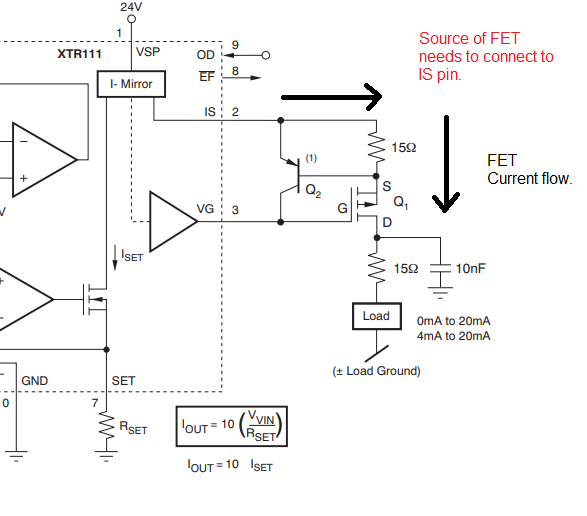
OD tied to GND. VSP is 24V. Q2 is KST2907AMTF and Q3 was at first SI2319, then I changed it to BSH201 since I found information that gate capacitance should be below 500pF, but it did not help. There is no 15Ohm resistors implemented in gate-source chain. Also there is no C3 capacitor filtering output. What can be a problem?

Thank you!

  • Hi Kirill,

    As I understand things, this is a custom PCB design (not the XTR111-2EVM). Can you kindly post the complete schematic?  If possible, please also post the layout gerber plots.

    - Is the XTR111 exposed thermal pad connected to GND? 

    - Is the load referred to the same GND potential than the XTR111 ground?

    - You have mentioned you have tested an LED with 1.5V across and you obtain no current (or low current only). What is the expected voltage drop on the LED when turned on, around 2V?  If you use instead a 250-Ohm resistor load referred to GND, what is the voltage across the load when VIN=2V? What is the status of the EF flag when the load is connected and you don't obtain the required output current?

    - Is this occurring on several XTR111 devices or only one XTR111 has been tested?  If only one device has been tested, please replace the device with a fresh XTR111 and test again.

    Please note, although I don't believe this necessarily is the issue, the 15-ohm series resistor between IS and the source of the external P-FET is required and works with the PNP transistor as an external current limit circuit.  It helps prevent fast transient currents that may occur and damage the XTR111 device when the load is connected and disconnected.  Please review the "External Current Limit" on p.13 of the datasheet. 

    We will be happy to review the schematic and layout in detail.

    Thank you and Regards,

    Luis

  • Voltage drop across LED at 10mA is 2V.

    Load is connected between output and GNDPWR.

    Tried second channel - same situation.

    Here are schematics and layout:

  • Hi Kirill,

    Thank you for the schematic.  

    The XTR111 'IS' pin requires a connection to the source of the P-FET for the current of the XTR111 'I-Mirror' to flow. 

    Notice, the current flows out of the IS pin, through a series resistor, and through source and drain of the FET, to the load.  On the schematic above, the source of the P-FET is not connected through any path to the IS pin (only to the base of the PNP transistor, which will not provide any current).

    You can quickly correct this by placing a small series resistor between IS pin and the P-FET source.  The 15-ohm series resistor is recommended so the external limit PNP current limit circuit works avoiding large, fast transients  when disconnecting and re-connecting the load. See figure below. 

    Thank you and Regards,

    Luis

  • My bad!! My eyes become blind. Thank you!