This thread has been locked.

If you have a related question, please click the "Ask a related question" button in the top right corner. The newly created question will be automatically linked to this question.

INA226: Wide current range application with uA precision needs

Part Number: INA226
Other Parts Discussed in Thread: INA228, INA229

Hi,

I'm looking for a smart solution to cover a pretty wide range from 1uA to 1.5A, currently looking at INA226

  in the 0-1mA range, I would be ok with a precision of 10uA
  in the 1mA to 100mA range I expect 1mA 
  and for 100mA to 1.5A a more coarse 10mA precision would be ok.

There are some power-profiler solutions out there utilizing 3-4 shunts with analog switch-overs to ensure the relevant series-resistance is used when the one below overflows. works, but fairly complex circuit so I'm looking for something more simple/compact.    

based on the INA226's input range, would a fake resistive load be an option to get things into range when measuring things in the lower current ranges, say 1uA to 1000uA?

  • Hello,

    Thank you for using the TI forum. Have you considered using the INA228 (I2C) or INA229 (SPI)? These are very precise devices that would be a better fit for this application than the INA226. 

  • I've looked at INA228, but with the high shunt values required by it (100mOhms) the drop will be too high at the 0.5-1.5A range, i.e. 150mV  @ 1.5A load. 

    Noted that the online calculator for IN228 gives %3.7 error @100mΩ shunt

    Any suggestions on how to get both good accuracy in the 1-100uA range as well as the higher current ranges? 

  • Hello,

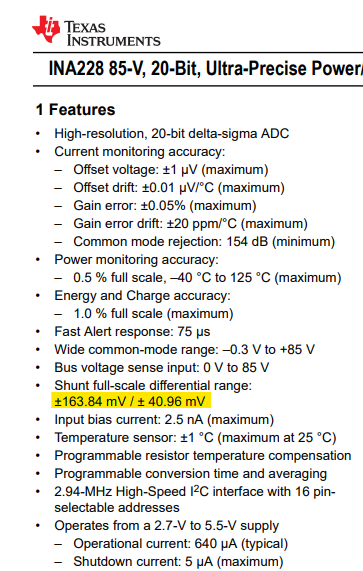
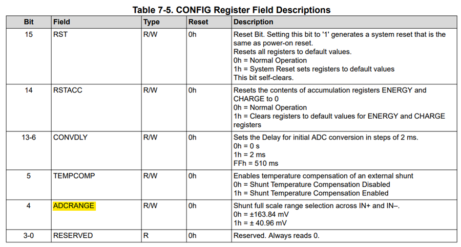
    Did you see that the INA228 has an adjustable gain? You can have a full scale range of ± 40.96 mV if you like.  Then you could use a shunt closer to 25mΩ.

  • need to review it again, just experimented with the web-simulator for it, and below 10mA error percentage starts to reach 5% plus

    perhaps just the tool, but lowest value I can enter is 100uA

  • reading the datasheet, can't find any info around adjustable gain, lemme know where you see this

  • So the full scale range is mentioned on the front page of the datasheet, and selectable in the register settings:

    Ya, the tool is not useful for currents less than 0.0001A.  Either way, the INA228/9 are the best digital devices we have at the moment, so it would still be an improvement from the INA226.

  • Thanks Mitch,

    Sorry that I missed it in the datasheet, I was looking for gain or PGA and such.. 

    The challenge is still how to make this work with one fixed shunt/sense-resistor.
    if we need accurate sub 500uA range, the resistance will cause too much drop at higher loads... 

    curious if you've seen any smart implementations using dual shunts just to get two ranges,
    either by auto-switching using discrete analog (in my case will take up too much board-space)...
    or perhaps by using the ALERT pin that can assert when these happen, i.e. could just control a mosfet to engage a higher shunt resistor...

    thoughts?

    --

    7.3.1.2 Alert Pin

    • Shunt Voltage Over-Limit (SOL)

    • Shunt Voltage Under-Limit (SUL)

    • Bus Voltage Over-Limit (BOL)

    • Bus Voltage Under-Limit (BUL)

    • Power Over-Limit (POL)

  • Hello,

    Sensing with such a wide dynamic range is definitely a challenge, especially with one fixed shunt.  I found this document that may help: https://www.ti.com/lit/sg/slyb194d/slyb194d.pdf. (This document was written before the INA228 came out, so it isn't specifically mentioned, but is still a great choice). One thing to note, is that you will likely have to calibrate your system at the lower currents. 

    I know sometimes people do multi-shunt solutions, and I'm sure the ALERT function could be helpful for that, but you mentioned that you wouldn't have the space. 

  • thx, great document and thanks for the assistance!

  • You're welcome!

  • actually, one more thing,

    The challenge with both INA226 and INA228 is that both has an input offset error (10uV and 1uV), so with a low resistance shunt (25-50mOhms) we end up in a situation where the lower-range <100uA is hard to measure.

    So an idea that came up here is to add a fixed fake-load to bring it just over the input offset.
    Please share your thoughs on this method.

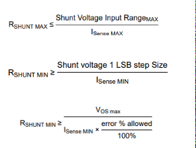
    I'd also like to understand what "I sense min" means. i.e. is this the minimum current we can measure OR the step-size?

  • Hello,

    Adding a fixed fake-load would only make sense on a unipolar device where the output is not being driven as low as you need.  Since this is a bi-directional part, this would essentially just add an additional offset to your system.  A better method would be to calibrate the offset out. 

    For those equations, in general:

    For the INA228, there are no PGA Bits, and the ADC bits would be 19 (because it is 20 bit, but 1 of those bits is a sign bit).

    You can find out more about this in the app note "Getting started with Digital Power Monitors" found here: https://www.ti.com/lit/an/sboa511/sboa511.pdf. Note that the screenshot for ISenseMin was taken from the included tool that is linked to in the introduction. 

    Also, note that if you want to actually be able to measure ISenseMin, then you should also consider the formula: 

    MaxExpectedCurrent <= ShuntVoltageInputMax/Rshunt

    (See the last paragraph of section 7 in the referenced document more info on this.)