Other Parts Discussed in Thread: ADS1119, ADS1248, ADS1148, INA821, INA818, INA333
Hi,
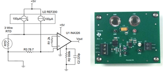
my customer wants to build a solution for radiometric measurement with a PT1000.
Requirements:
- 4.5 - 8m wire between PT1000 and pcb
- 2-Wire measurement is mandatory
- external Ref
- ADC should be the ADS1119
He read the Document SBAA201- RTD Ratiometric Measurements and Filtering Using the ADS1148 and ADS1248 Family of Devices. To build this he needs an external current source for ADS1119.
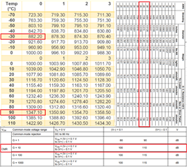
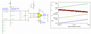
- Q1: Are the recommended steps for common-mode and differential filtering enough to reduce emitted interference
- Q2: Are there special circuits for the current source which have a good immunity against interference. The customer read about the current sources in SBVA001 and SNOA481b (3.1.1.1 Current Source)
Can you please also recommend parts.
Thanks
Jan