This thread has been locked.

If you have a related question, please click the "Ask a related question" button in the top right corner. The newly created question will be automatically linked to this question.

LM318: LM318 TINA AC analysis

Part Number: LM318

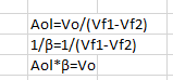
I need an open-loop circuit (no feedback) to generate open-loop gain (AOL), 1/β, and loop gain (AOLβ) curves

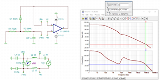
the below schematic is a sallen key filter, there are two input VF1 and VF2, is the simulation right?

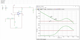
or i need to modify the expression as follow:

  • In order to perform a phase stability analysis?

    I would do it this way:

    user_lm318.TSC

    Kai

  • Hello,

    The method you are using still provides a feedback path to the positive input of the op amp and does not fully "break the loop" require for a stability analysis. For a circuit with positive and negative feedback, like the Sallen Key filter, you will need to use a different method to measure the phase margin. Below I have attached a snapshot of a presentation showing how to break the loop and where to measure the loop gain (Aol*Beta) to determine the phase margin of your circuit. 

    However, the op amp model is likely quite old since the device was released in 1976 so it would be good to verify that the op amp macromodel is accurate. I recommend taking a look at this blog post.

    Lastly, we may have a newer better device that will meet your design needs. I would be happy to make some device recommendations if you can share you op amp specification requirements.

    Thank you,

    Tim Claycomb

  • Thanks for your kindly reply, it is helpful

  • Now I use Bode100 to test loopgain of PCB, but for TINA simulation ,I'm not skilled at all, Thank you very much for your detailed explanation