This thread has been locked.

If you have a related question, please click the "Ask a related question" button in the top right corner. The newly created question will be automatically linked to this question.

INA118: INA118 for current sensing

Part Number: INA118
Other Parts Discussed in Thread: TINA-TI, INA828, INA188

Dear Supp (see ort,

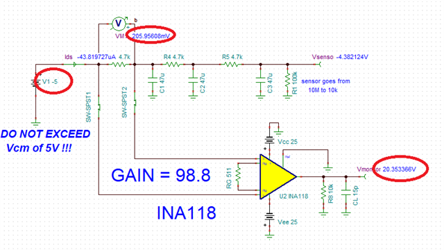
I have to measure the current flowing into a sensor showing a pure real impedance in the range from 10M to 100k. Please see the attached TINA-TI schematic.current_sensing_with_INA118.TSC

The current flowing into the sensor is measured by probing the voltage across a 4.7k resistor (see schematic).

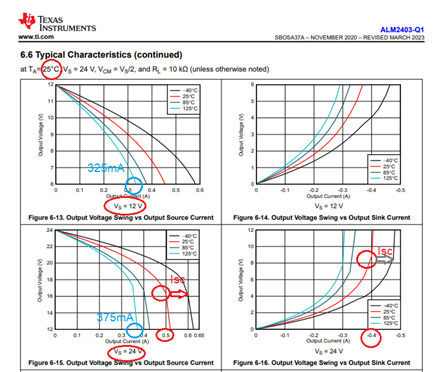
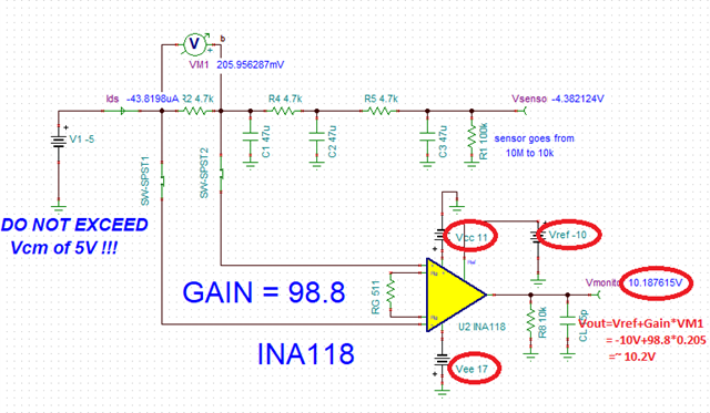
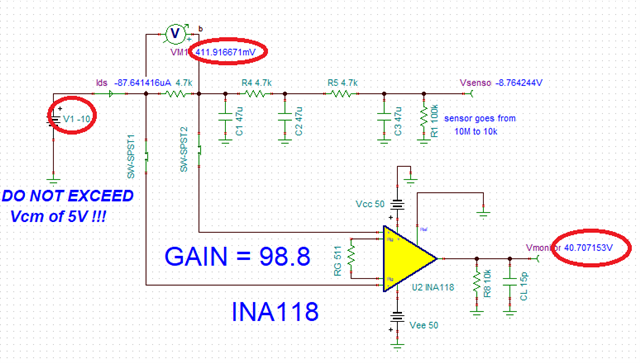
I used the INA118 configured with a 100x Gain. According to the datasheet, the tolerated Vcm should be in excess of 5V. However, in my application, I could be forced

to power the sensor with a voltage up to 10V, so the 5V limit could be a problem.

Moreover, I have to preserve the noise voltage appearing across the sensor, so I guess using a sero-drift is not a wise choice.

Do you have any suggestion/advice ? Should any other INA be considered ? Is a FET input INA to be considered ?

Thank you so much for your help.

Best,

Alberto

  • Alberto,

    There is more than one issue with what you try to do.  You say that you want to measure the current flowing into a sensor showing a pure real impedance in the range from 10M to 100k using shunt resistor of 4.7k, however, even with sensore being powered by -5V this becomes impossible on +/-12V supply since the differential voltage for 100k sensor would be over 200mV.  In the gain of 100 with Vref=0 this would require the output to go to 20V, which is not possible on 12V supply - see below (btw, I used +/-25V supplies ONLY for illustration where the output would need to go). 

    Thus, if sensor may be as low as 100k, you have to adjust the supply voltage and Vref as shown below unless you lower the gain or lower shunt resistor value.

    Therefore, in order to assure linear operation of INA118 you must consider the input and output voltage ranges based on the shunt resisor, supplies, gain and Vref.

    For V1 of -10V and R1 of 100k, VM1 would be above 400mV and thus in the gain of 100 the output would have to go to 40V - this is clearly not possible on +/-12V supplies.  Therefore, you must consider all required trade-offs between V1 input range, gain and supply voltages before you may arrive at final solution (disregard +/-50V supplies - it's used only for illustration of the required output voltage range).


  • Dear Marek,

    thank you so much for your analysis. I will take care of the combination of supply, gain and Vref, in order to keep the INA in the

    linear region.

    Just let me know if you suggest any other INA for this application (for istance, with a wider Vcm).

    I have to avoid to inject current from the INA to my sensor: do you agree in avoiding zero-drift architecture ?

    Thank you again for your help.

    Best,

    Alberto


  • Hi Alberto,

    You may consider a newer part like INA828 with similar specifications but much lower price.  

    Please download INA Common-mode Input Voltage Calculator to determine linear conditions for given supplies, gain, Vref:

    https://www.ti.com/tool/INA-CMV-CALC?keyMatch=VCM%20VS%20VOUT%20CALCULATOR&tisearch=search-everything#downloads

    The INA118 maximum IB of 5nA is just 0.01% of shunt current for 100k sensor (Ishunt=~5V/100k=~50uA) and 1% for 10M sensor. 

    You'll get 10x improvemnt using INA828 with max IB of 0.6nA at 25C (~0.001% for 100k sensor and ~0.1% for 10M based on -5V supply).

    I would probably avoid zero-drift instrumentation amplifiers like INA188 because of possibility of problems related to conversion of IB spikes across mismatched input impedances into a measurement error.