- Ask a related questionWhat is a related question?A related question is a question created from another question. When the related question is created, it will be automatically linked to the original question.
This thread has been locked.
If you have a related question, please click the "Ask a related question" button in the top right corner. The newly created question will be automatically linked to this question.
Hi Augustin,
You did not post the waveforms that you reference in your post. Are the power supplies regulated and bypassed? Have you also confirmed that the PD pin is remaining high after power on?
Best,
Sam
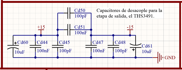
you might try putting some 10ohm R's in series with the supplies with the decoupling caps at the device pins
Hi Agustin,
1. Have you seen footnote (2) of section 7.1 of datasheet? Abrupt connection to the bench test power supply can turn-on the internal edge-triggered ESD absorption device of THS3491 and destroy the OPAmp. Adding resistances in series to the supply voltage pins, as already recommended by Michael, can sufficiently slow down the abrupt turn-on and help to protect the THS3491.
2. The absolute maximum supply voltage of THS3491 is +33V or +/-16.5V. Slight misadjustment of bench test power supply voltage could destroy the THS3491.
3. Some bench test power supplies can emit riskful overvoltages during turn-on. If this is the case, have the supply lines to the THS3491 disconnected when turning-on the bench test power supply. After turning-on, adjust the supply voltage to 0V, connect the supply lines to the THS3491 and turn the knob of bench test power supply to the desired supply voltage.
Kai
Hey Kai,
The supply dV/dT is a good point, especially if there is any inductive kick on those pins. The actually max static supply can likely be much higher than stated - early testing on the device showed >45V volt static with no breakdowns, but not supportably by PDK limits.
That 10ohm series will take care of the dV/dT issue as well (if the supply decoupling is on that other side.
Hi Sam (and everyone)
I'm trying to get more ICs and since I'm in Argentina that would take same time (say 1 month).
I'll let the thread open and measure my power supply transient. Once I get my hands on the ICs I'll let you know.
Thank you very much.
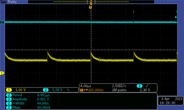
Here is the power supply startup. It's pretty clean (don't know where the 8% overshoots come from).
So I'm gonna add the 10 ohm resistor and wait for the new chip to arrive.

Ok. New ICs have arrived.
I added two HI1206N800R-10 ferrite beads (one for each supply) as used in the evaluation board of the THS3491DDA and reduced the voltage to 12V. It stills blows up. I couldn't even measure the power supply voltage with the scope: I got a 2.5 V pulse and then it goes back to 0 V.
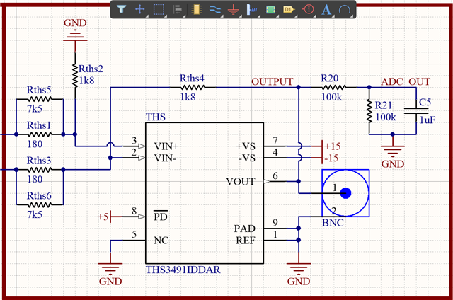
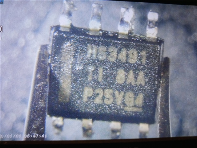
Is there something about the PD pin? I connected it to 5 V while in the EVM it's connected to VS+..
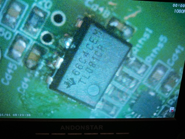
Just to be in the safe side, the pin 1 is the bottom left one, correct?
(ic picture above)
I know that a ferrite is now the same than a resistor.
Anyway, what about the pin 1 and the PD pin voltage?
The ferrite es 80 ohms. Im using the EVM circuit.
And I have only 2 ICs more, I cant keep blowing them up. They arent cheap.
Hi Agustin,
Based on the image on the THS3491DDAEVM page, pin 1 should indeed be the bottom left one in your image (with the line to it).
Cheers,
Jon
Hi Agustin,
does it work now with /PD connected to Vs+ and 10R resistors inserted in the supply lines?
Kai
Hi Agustin,
Are there any other devices that are powered by these rails? I would feel better if we could confirm that there is not a power polarity issue or something else going on with the supplies. Even if there is a PD pin issue, it shouldn't blow the IC. If you probe the supply pin pads on the PCB after removing the chip from the board, do the rails look normal and stable with no current draw?
Best,
Sam
Even if there is a PD pin issue, it shouldn't blow the IC.
Well, if /PD is powered while the supply voltage is down...
Kai
There are no other ICs connected to -15 V and the only one connected to +15 V is a LM4040.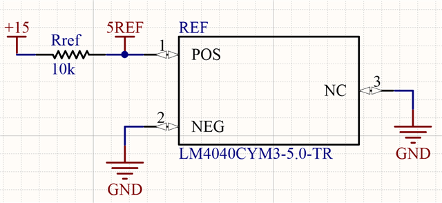
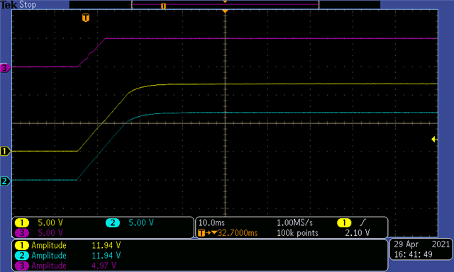
I'm checking and double checking everything. I believe there is no power polarity issue since the LM4040 works fine (without the THS soldered). This is the positive power rail before (yelow) and after (blue) a 33 ohms resistor. Thi purple (or magenta) is the 5REF signal (see prev picture).
Hi Agustin,
can you start with a much lower supply voltage? Eventually, provided by batteries?
Kai