This thread has been locked.

If you have a related question, please click the "Ask a related question" button in the top right corner. The newly created question will be automatically linked to this question.

INA118: sensing current in the 0-1uA range

Part Number: INA118
Other Parts Discussed in Thread: INA828, INA188

Dear Support,

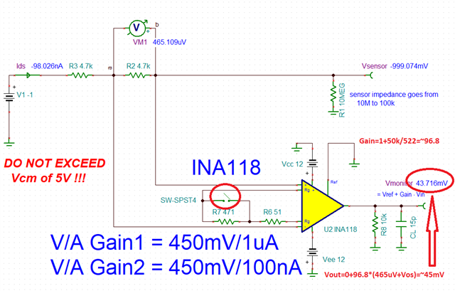
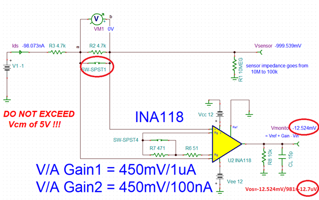
I used the INA118 to sense the current flowing into a sensor. The sensor is biased with a V= -1V. The current flowing into the sensor span the range from 0 to 1uA.

Please see the attached schematic.

current_sensing_with_INA118_E2E.TSC

In order to calibrate the system, supply voltage is provided by a Keithley SMU, able to measure the output current with pA resolution.

Unfortunately, the current read-out by the INA118 does not match with the value shown by the Keithley. The INA output shows a current which is lower than the one

displayed by the Keithley by almost 50nA. I have tested the SMU and I have found it to be perfectly fine: the problem is in the INA118 circuit.

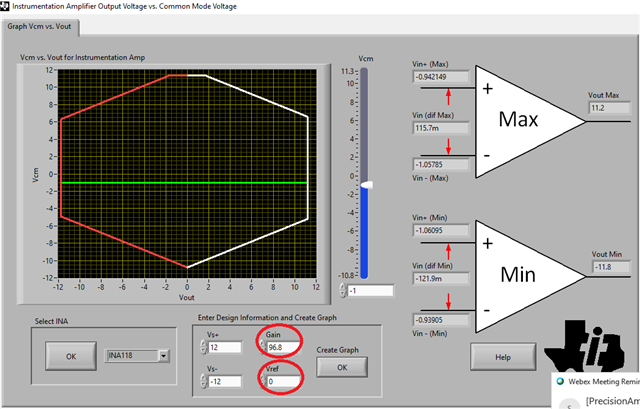
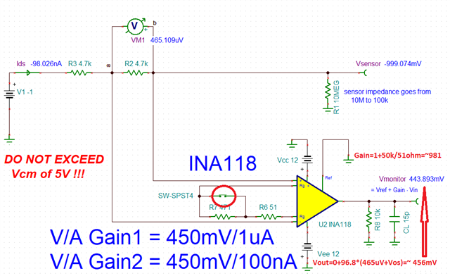
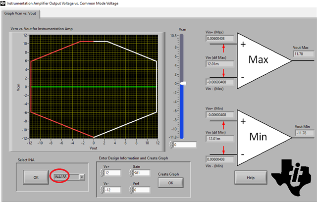
 I have accurately measured both the sensing resistor (4.7k +/- 0.1%) and the Gain Resistor (471+51 +/- 0.1%). Also, the INA CMV is not violated.

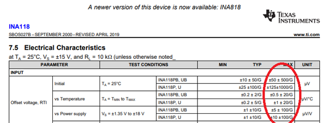
I am wondering if such a difference between the SMU readout and the INA118 could be due to its input current bias/offset . I also changed the INA118 with a INA828 (lower bias/offset), without any improvement. My measurements are basically in DC, so, if beneficial, the bandwidth could be drastically reduced. Should I filter the INA inputs? In such a case please suggest me a filter topology to be inserted  just before the INA, not disrupting its CMRR.

I really appreciate receiving your advice.

Thank you so much for your support.

Best,

Alberto

  • Albero,

    The issue is with your gain calculation.  It is: G=1+50k/Rg.  Thus, it is not 299 as you show in your Vcm vs Vout calulcator but rather G=1+50k/522=96.8 or G=981 (Rg=51ohm) - see below.  Also, in your Vcm vs Vout graph you use Vref=-5V but in you schematic Vref=0 - I used the latter.

    For gain of 96.8 and Vref=0, simulated Vout is 43.7mV (close to 45mV calculated without including offset).

    For gain of 981 and Vref=0, simulated Vout is 444mV (close to 456mV calculated without including offset) - see below.

  • Dear Marek,

    thank you for your reply. In my tests, I used Rgain = 51 Ohm, so the Gain = 1 + 50k/51= 981.

    In your formula, you add Vos (50uV) to (V+ - V-), then you multiply by the gain. By doing that, I nearly obtain the value neasured by the

    Keithley SMU. How can I cancel/moderate the Vos effect on Vout ? Or can you suggest me a different INA with lower Vos (50uV seems to be

    already a very low Vos) ?  Does a FET-input INA give a more accurate output ?

    My best,

    Alberto

  • Alberto,

    The input voltage offset of INA118 has a Normal Gaussian distribution and thus may vary unit to unit with its limits as defined in the datasheet below.  For this reason, in order to take a precise measurement, you may NOT assume 50uV offset or -50uV - you must measure it.

    Since you already calibrate the system, you may add a switch across R2 shunt resistor to calibrate the offset.  Shorting R2 will result in a zero differential input voltage and thus you may then use the output reading to back calculate the actual input offset voltage, Vos - see below.

    In the example below with Vref=0, Vos=Vout/Gain = -12.524mV/981 = -12.7uV

    Zero drift instrumentation amplifiers, like INA188, would have the lowest input voltage offset and offset drift BUT to get the most precise measurement calibration is the way to go as descibed above.

  • Dear Marek,

    thak you so much for your help and assistance. E2E is a GREAT service !

    Kind Regards,

    Alberto