This thread has been locked.

If you have a related question, please click the "Ask a related question" button in the top right corner. The newly created question will be automatically linked to this question.

INA260: INA260 design help

Part Number: INA260

Hi team,

I have designed a small breakout board to test a number of INA260 current monitors on the same I2C bus. I am getting widely fluctuating and inaccurate readings from each of the INA260 ICs. You can see readings from one chip when no current is supplied and when 3A is supplied. All chips exhibit the same behaviour.
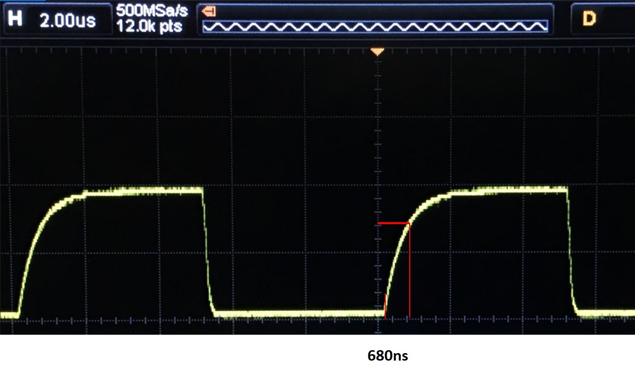
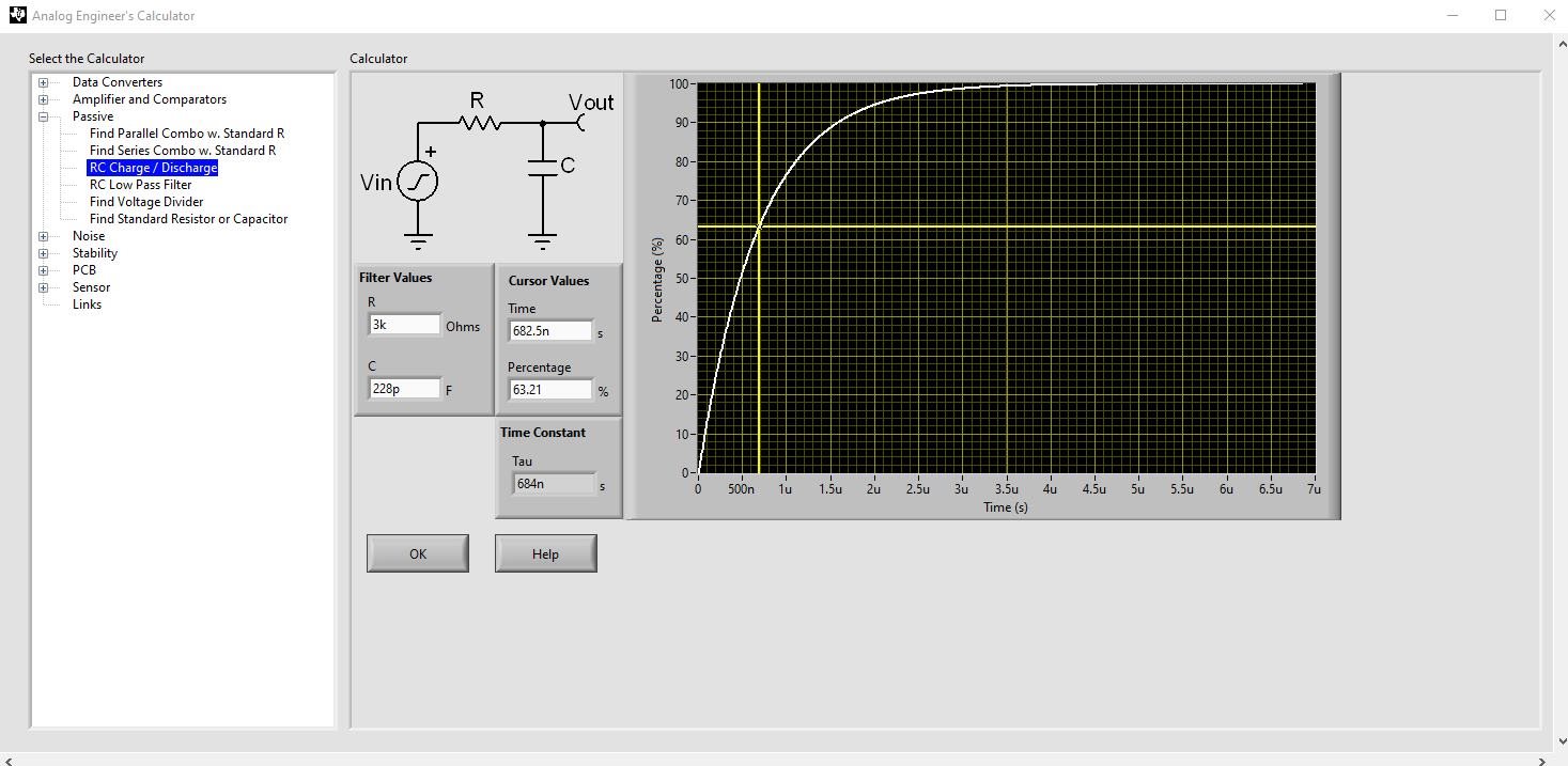
I have noticed that the I2C signals rise time are quite slow (rise time ~1.1uS @ 100kHz). In the image below, the yellow trace is SCK and the blue trace is SDA. Could this cause misreadings? The capacitance between both SDA/SCK and ground is abnormally large - ~3.8uF (on the board with four INA260 shown below). I subsequently halved the pull up resistors to 1.5kOhm and the rise time dropped to ~500ns, which should be within I2C specs for a 100kHz clock. The problem still occurs. I’m including a video of oscilloscope readings where we clearly see the LSB of the packets sent from the INA260 fluctuating. This leads me to believe that there is another issue besides the high capacitance of the I2C lines. I’d still like to resolve this problem because I need as low of a power consumption as possible.

I am at a loss as to what could cause this capacitance. A bare PCB shows no capacitance when probed, and one PCB populated with a single INA260, its 0.1uF decoupling capacitor and pin headers reads ~2uF. I even removed the decoupling capacitor to measure the capacitance and found the same value. There are no other components on the board at that point.
I’ve included the schematics and a screenshot of the board design (with the SDA trace highlighted as an example).

So the first question would be, what could be the cause this large capacitance? And the second question would be, besides this issue, what else could cause the fluctuating readings?

INA260_Fluctuating_Readings.zip

Best regards,

  • Hello Zhounghui, 

    I could not open the HEIC files or the .mov file.  From what I can see I also cannot explain what the issue with the capacitance is due.  The datasheet typical value per digital pin is 3pF so this really does not make sense. If you can give me the pictures in a different format.  I tried downloading a reader.

  • Hi Javier,

    Sorry about that, here’s a download link: https://drive.google.com/file/d/11hXiE4wHPUGCf-W06yPriBu3nhL58kmd/view?usp=sharing 

    please check the pictures,

    Best regards,

  • I am looking into this now.  I will give you an update soon.

  • Hello Zhonghui,

    I do not know what is going on with this setup but I do not believe it is an issue with the communication.

    I see 3A but the measurements vary from 1.4A and so on.  Do you have 2 in parallels connected?  What is changing in the system?  Is the current changing?  Is the voltage changing?  Are you able to measure the current with another instrument to verify?

  • Hi Javier,

    Yes, the 3A goes through two parallel INA260 (for reduced power consumption) so it should give a solid and constant 1.5A (+- a few % depending on the relative total shunt resistance of the two paralleled INA260). In the final application, I’ll be summing the two, but these screenshots were more meant to indicate the fluctuating results (from 945mA to 1573mA in 1s, for example). The 3A is solid DC (verified by a good multimeter). Both the supply voltage (3.3V) and the bus voltage are not changing. I should note that I left the VBUS pin floating because I don’t need that measurement. Could this cause an issue somehow?

    Thanks a lot.

    Best regards,

  • Zhonghui,

    I do not think floating the bus voltage is an issue. 

    The only thing I can think of is the current is not balanced on the two parallel INA260.  Have you attempted to measure both and see if it adds up correctly?  Have you attempted to only connect one device and verify?  If the current is supplied with a switching power supply and there is not enough capacitance to keep the voltage stable you could be switching noise and cause some spikes seen within conversion time that may not be seen with a meter.

    Have you attempted different conversion times?

  • Hi Javier,

    I have to thank you for having me look into this voltage noise. When I placed a capacitor across the shunt + and - pins on the INA260, the readings became stable and precise as they should be. There was 10mV peak-to-peak across the shunt. I’m wondering if this has to do with the fact that the power supply had to supply 3A but without much load (only ~90mW as it went through the INA260 shunt and straight back into the power supply), which could upset the output filtering stage of the power supply. Maybe it would be a good idea to suggest adding a capacitor as a good practice in the datasheet.

    However, the high capacitance on the I2C lines persists. Any idea on what I could try?

    Thank you very much!

  • Hello Zhonghui,

    I think your capacitance measurement is not accurate.  I looked at your time constant and your rise time and with 1.5kΩ and 2µF that would give a time constant of 3mS.  Your scope shots showed that the signal goes to voltage in about 2µS.  

    I think the capacitance is much lower than your measurements.

  • Hi Javier,

    Sorry for the late reply, I had to work on another board.
    I’m wondering if the slow rise times could be caused by some series resistance in the bus somewhere in the circuit or internally in the chips somehow? That would throw off the time constant of the multimeter capacitance measurement as well I think. I’ll try to find some other I2C sensor board to double-check if the slow rise times could come from the microcontroller.
    Thanks,
  • Zhonghul,

    If the INA260 is not on or have power there could be an ESD cell activated that will cause some leakage current.  Please make sure the device is on when making the capacitance test and nothing else is connected.  This is dependent on the current driven by capacitance tester.

    I would also recommend you disconnect all other connections and power the device to measure this. 

  • Hi Javier,

    I tried measuring the capacitance between SDA/SCL (they didn’t go to anything and had not pull-ups) and GND while the INA260 was powered by 3.3V like you recommended. My multimeter isn’t able to read the capacitance in this configuration.

    I also tried communicating to the INA260 with another dev board (initially Arduino and now STM32 Nucleo), but I’m getting the same rise times. What typical rise times do we expect? I know the protocol requires rise times below 1000ns, but what is typical for a simple 3.3V embedded application?
    Thanks,
  • Hello Zhounghui,

    The specs are to cover all the temperature and other variations possible.  I do not believe the device will not function if rise time is not below that amount but this is due to all the other timing variations as well.

    For your capacitance I calculated you have about 228pF on the line.  Most scope probes add about 10pF and your layout may be adding the rest.  I used the Analog Engineer's Calculator and is pick displayed below.  The time constant can be calculated when the signal gets to about 63.2% of the final value.