This thread has been locked.

If you have a related question, please click the "Ask a related question" button in the top right corner. The newly created question will be automatically linked to this question.

XTR115: About the case of connecting without RL

Part Number: XTR115
Other Parts Discussed in Thread: XTR116

Hello,

If the customer supplies 24V and connects without RL, does it output 4-20mA without breaking?
(The customer wants to know what happens if both ends of the RL are shorted due to a mistake during inspection.)

Best regards,
DDdoor

  • HI DDdoor,

    The XTR115 output current linear range is from the under-scale limit (limited by the current consumption of the complete 2-wire current transmitter circuit)  to a maximum output current of 25mA.

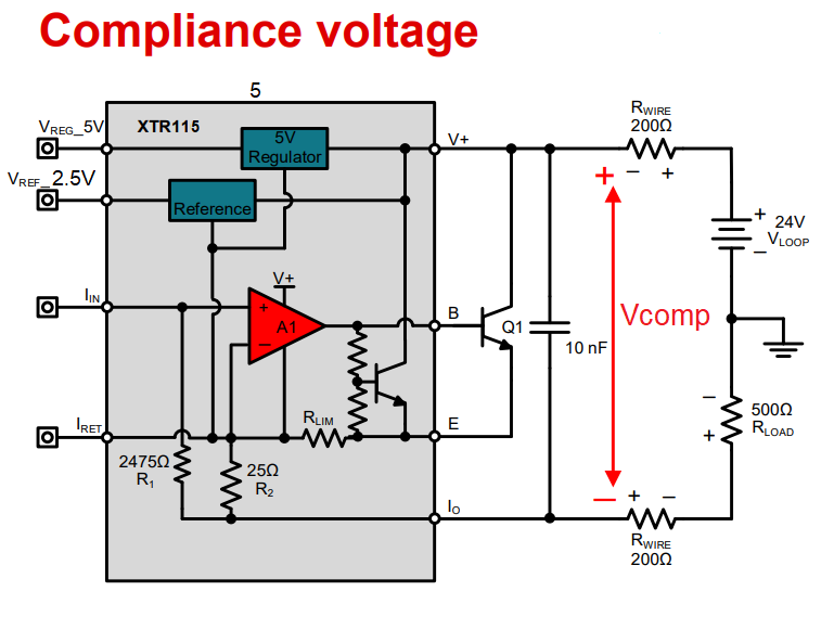
    The device can supply this output current in this range as long as the Loop+ supply is within the range of +7.5V to +36V, the load resistor is referred to the loop supply GND, the XTR115 minimum compliance voltage rating of +7.5V is met (see Vcomp on diagram below), and all the device pins are within the specified linear region, an as shown below.  The +5V regulator and the +2.5V voltage reference are referred to the IRET potential, where IRET is allowed to float above the loop supply ground.

    Are you discussing a condition where the loop supply is Vs=+24V, I-Out is shorted to the loop supply ground with Rload = 0-ohm?  If this is the case, the XTR115 will still supply an output current as a function of the transfer function, Iout = Iin*100. 

    If this is not what you meant, please provide a detailed diagram or schematic showing the XTR115 voltage supply connections and bypass capacitors, external NPN transistor, XTR115 input drive circuit and the voltage potential that the shorted RL is referred to.

    Thank you and Regards,

    Luis


  • Hi DDdoor,

    I have not heard back from you, I assume the question was answered, however, please let us know if you have additional questions.

    Below is a link to a 2-wire XTR116 reference design (same family as XTR115) that discusses EMC/EMI protection:

    2-wire, 4-20mA Transmitter, EMC/EMI Tested Reference Design
    TIPD190

    Below is a link with additional information about 4-20mA current transmitters and 2-wire transmitter frequently asked questions:

    [FAQ] Designing with 4-20mA current loop transmitters (XTRs): FAQ links

    Thank you and Regards,

    Luis

  • Hello Luis,

    Thank you for your reply.


    >Are you discussing a condition where the loop supply is Vs=+24V, I-Out is shorted to the loop supply ground with Rload = 0-ohm?

    yes. Customers are worried about this that you guessed.

    >If this is the case, the XTR115 will still supply an output current as a function of the transfer function, Iout = Iin*100.

    Please tell me a little more about this.

    If there is no RL, a negative potential of 24V is directly applied to the Io terminal,
    At that time, what is the state of the Io terminal?
    Does the terminal output a constant current? Or will the terminals be damaged?

    Best regards,
    DDdoor

  • Hi DDdoor,

    If RL is shorted (a small resistance short, close to 0-ohms) connected to the ground of the loop supply, (GND is at 0-Volts, no negative voltages involved), the IOUT terminal will be connected to GND (0-Volts), and the device will supply the output current through the short  or 0-ohms resistance.  No damage should occur on this specific condition.  Please note, the XTR115 is powered by a uni-polar, positive supply, with V+ = +24V, and the loop supply GND is at 0-volts and therefore, no negative voltages are involved.  

    Damage will occur if the Absolute Maximum Ratings of page 3 of the XTR115 datasheet are exceeded.  For example, damage can occur if the potential between V+ supply and I-out exceeds 40V.  Connecting I-out to an external negative voltage below the loop supply ground can potentially cause damage if the voltage between V+ supply and I-out exceeds 40V.  Another example, damage can occur if the user reverses the polarity between V+ supply and I-out connections; or if I-out is exposed to a potential that exceeds the V+ supply.  

    Below is a link to a 2-wire XTR116 reference design (same family as XTR115).  The design includes output protection circuit recommendations for IEC61000-4 immunity and includes a bridge rectifier at the XTR 2-wire current transmitter output to enable functionality regardless of the polarity of loop supply and load connections.

    2-wire, 4-20mA Transmitter, EMC/EMI Tested Reference Design
    TIPD190

    Hope this helps,

    Regards,

    Luis