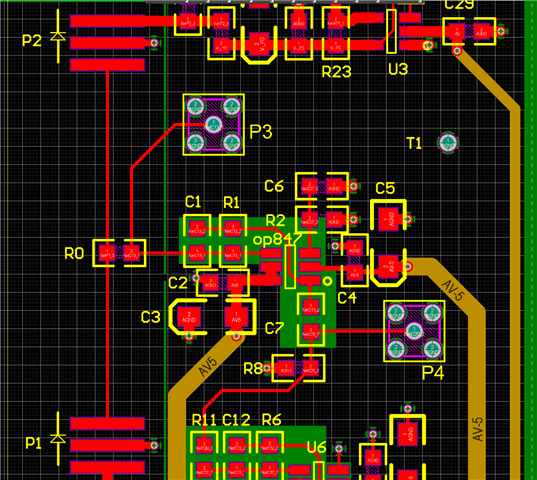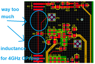
zoom in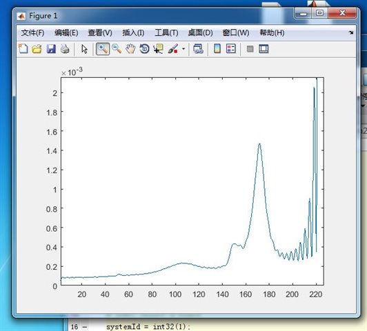
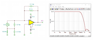
schematic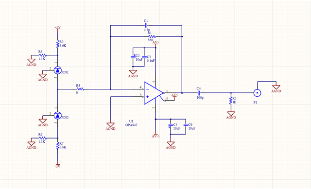
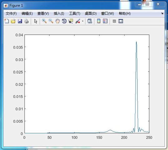
how to make the freq spectrum become flat?the cap of the PIN is about 9pF,so two PINs constitude a cap of 18pF.
Original question:

zoom in
schematic
how to make the freq spectrum become flat?the cap of the PIN is about 9pF,so two PINs constitude a cap of 18pF.