


Hello, TI expert.
I am testing the LLC block by applying TL103WAIDR.
Spec is shown in the table below. (Max 360V / 3A output)

Before I change the CC circuit part (attached circuit diagram specification), the LLC output current ripple(Ip-p) is about 2A.
However, the circuit was changed so that CC control was not possible with the above specification.
And when the output current was measured with the changed specifications, the output ripple Ip-p increased to 5.65A
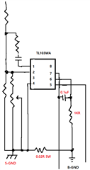
The changed part of the CC circuit is as follows.
1. R362, C352 NC
2. Add 1KR resistor between 6pin-B-GND
3. Add 0.1uF MLCC between 6pin-7pin
4. Connect pin 2, 3 (ground on CV side) and 4 pins S-GND
5. Connect 0.02R 5W sensing resistor between S-GND and B-GND
We are going to solve this problem by changing the TL103WAID IC circuit.
Q1) Is there any part to modify the CC,CV circuit to reduce the output current ripple?
Q2) In the CC,CV part of the schematic, is there any part to be modified for complete control? (Especially on the CC,CV compensation circuit side)
The circuit diagram and output current waveform are attached. Please check.
Thank you.
-. Output current before CC circuit change

-. Output current after CC circuit change

