This thread has been locked.

If you have a related question, please click the "Ask a related question" button in the top right corner. The newly created question will be automatically linked to this question.

LM318: Compatible alternative for National LM308N

Part Number: LM318
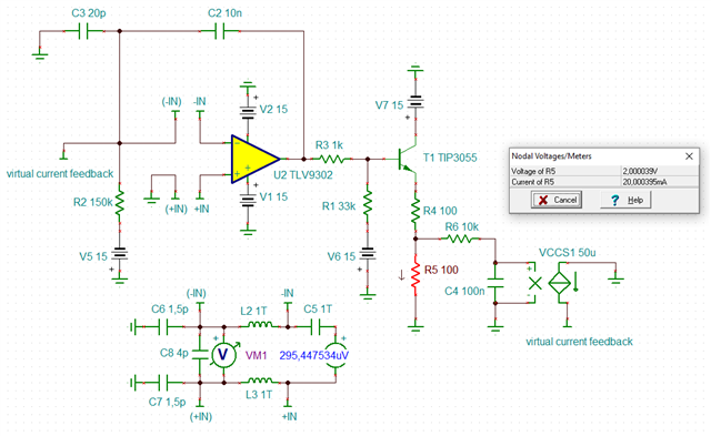
Other Parts Discussed in Thread: TLV9301

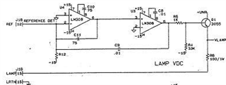
We recently purchased TI LM318P thinking that it was a compatible replacement for the National Semiconductor LM308N (we used these for years)

Unfortunately the LM318P did not work in our application (suitable package but did not function electronically)

Does TI have a suitable device for replacing the LM308N ? 

  • Hi Steven,

    Do you have a datasheet of the LM308N? I can't seem to find one on TI.com. 

    I did some searching and saw that the LM308N has a compensation pin to set the bandwidth. The LM318 appears to have a similar function, although I'm not sure if it is identical.

    Can you list the specs you need for the op amp? We likely have a much better newer device that will meet your needs.

    Thank you,

    Tim Claycomb

  • Thank you for the prompt response.

    The LM308N is manufactured National Semiconductor

    LM108.pdf

    I don't have on-hand the specs needed for our application, if required I would need time to get them...

    Another manufacturer's chip that works is the NTE938M

    nte938.pdf

    Hope this helps

  • Hi Steven,

    Do you need a pin to pin compatible device? There are going to be very few options that have the comp pin like the LM308 and LM318. 

    For specifications, we can start with supply voltage, input voltage range, output voltage range, bandwidth, and circuit configuration (non-inverting, inverting, etc.).

    Thank you,

    Tim Claycomb

  • Tim,

    I don't want to re-invent the wheel so yes a pin by pin compatibility is required

    These are used in boards we have been using for many-many years.

  • Hi Steven,

    In that case our options are limited. The LM318 is one device I know of that has the comp pins. I'd have to look to see what older device we might have with the comp pin. Maybe we can get the LM318 working in your application.

    Can you explain why the LM318 is not working in your application? What are your failure symptoms?

    Typically to troubleshoot issues we'll need to know supply voltage, input and output voltages, and configuration (or schematic preferably).

    Thank you,

    Tim Claycomb

  • All,

    The LM308 is de-compensated, and uses an external capacitor to set the bandwidth.

    The issue is the capacitor. What value is the capacitor on pins 1 and 8? Does the capacitor go between 1 and 8? Or between pin 8 and GND?

    With a 30pF cap between 1 and 8, the GBW is about 800kHz.

    There is a graph in the datasheet showing the open loop frequency response with various capacitors.

    Note that Cf is with the cap between pins 1 and 8, and Cs with the cap from pin 8 to GND.

    The basic pin-out of the LM308 is the standard  single op-amp, shared by many other op-amps.

    Once the desired op amp GBW is determined, then a suitable replacement can be picked and dropped-into the socket. Just be sure that the replacement device pins have N/C on pins 1 and 8.

    There are also some circuits that used the capacitor to boost the bandwidth. If the circuit has a capacitor from pins 1 or 8 to other parts of the circuit, then the circuit will need to be analyzed.

    So by answering the capacitor position question above, we can answer the possible replacement device options.

  • Hi,

    another advantage of the LM308 is its very low supply current. Because of this the LM308 was widely used in battery powered devices.

    Kai

  • I thank you for your time and efforts

    Perhaps I was a little naïve but I was hoping that TI had a cross reference guide so all that was needed was a manufacturer's chip number to find a TI compatible device...

    I apologize for quality of the schematic but it is all I have to work with (my original is just as fuzzy), here is part of the circuit drawing showing how the LM308 is used (there is another circuit but this is where we see the most failures).

    C10 (U4 pins 1 & 8) is actually now a 68 PF Capacitor

    C8 (U3 pins 1 & 8) is .01 UF Capacitor

    The reference signal is current generated by photoelectric cell (20 - 25 UA's selectable) created by the lamp. The circuit controls/maintains a constant reference signal.

    The 3rd a final LM308 used  in a different circuit (not shown) has a .1 UF Capacitor

    I hope you find this helpful

  • Hi Steven,

    interesting: the input stage of the second OPAmp isn't current protected. But because the output current capability of LM308 of the first stage is very limited, no damage will occur.

    Having two stages in this design looks a bit strange. With two todays OPAmp this will not work because the second OPAmp will turn the phase too much for stable operation. But here the LM308 is heavily slowed down by this huge 10n compensation cap. This circuit cannot simply be made to run with two standard OPAmps, I think.

    So I would take only one OPAmp and drop the second stage. And I think the TLV9301 might be a good replacement for the LM308:

    To be able to carry out a phase stability analysis I have implemented a virtual current feedback by the help of voltage controlled current source VCCS1. The idea is simple: The current trough the "lamp" R5 produces light and this generates current within the photocell. C3 assumes the detector capacitance of photocell.

    The circuit is designed to make the control loop lock in at a lamp current of 20mA. This is wild guess, I know, but as there is no further information on the circuit I had to speculate a bit.

    I also had to assume a "current to light delay" of the lamp. R6 and C4 form a time constant of 1ms.

    And here is the phase stability analysis:

    steven_lm308.TSC

    Looks stable.

    Eventually you might want to add two antiparallel diodes (BAV99 or else) across the inputs of OPAmp to help the loop to faster leave saturation conditions.

    Kai

  • Steven,

    Is the gain from the second op amp really needed? Have you consider removing it and replacing with a pin 3 to 6 jumper? (will probably be difficult for automated build)  There are other DIP single op amps to try, but most will have pins [1, 5, 8] open so the bandwidth won't be adjustable. So it is unlikely that they would be stable.