To eliminate the voltage signal with a phase difference of 90 degrees produced by AC sensing in signal transmission line, we want to design a synchronous detection circuit to pick original signal. Do we have any reference circuit or guide?
This thread has been locked.
If you have a related question, please click the "Ask a related question" button in the top right corner. The newly created question will be automatically linked to this question.
To eliminate the voltage signal with a phase difference of 90 degrees produced by AC sensing in signal transmission line, we want to design a synchronous detection circuit to pick original signal. Do we have any reference circuit or guide?
Hi Leonard,
The case is AC Internal Resistance Tester for battery. Through testing the ac voltage level when apply ac current to both sides of battery is the way to test internal resistance. As we know that the internal resistance of battery is usually mΩ level, the max peak-to-peak value of ac voltage we need to measure is 4mV, the min value could be 0.1uV.
As the below picture showed, each line has a ac voltage test line and a ac current line to apply to cathode and anode of battery. The electromagnetic field caused by ac current will cause a sensing voltage with a phase difference of 90 degrees on ac voltage test line.
To eliminate this sensing voltage, I think synchronous detection circuit or Lock-in Amplifier may solve the problem. So I'd like to know if we have any solution or reference design.
Thanks a lot~
Rayna
Thanks very much for the details, Rayna. I am routing this to the Battery Group to get their suggestions.
Regards,
~Leonard
Ruixin,
Unfortunately, CSPS doesn't have much in the way of guides regarding synchronous detection, but the methodology of such a circuit is pretty straightforward as Kai mentions. Do you know what frequency these AC waveforms will operate at?
Hi Kai,
The signal frequency is 1kHz. And the sensing signal is also 1kHz, but 90 degree phase shift compared to it.
Rayna
Hi Ruixin,
as the battery impedance is complex or, by other words, the equivalent circuit contains resistances, inductances and capacitances, the phase shift isn't constant. So you would need a dual phase lock-in amplifier. Correct?
Kai
Hi Kai,
The dual phase you mentioned means that lock-in amplifier has a range of lock-in phase based on reference signal, right?
Rayna
Hi Ruixin,
dual phase lock-in means that the excitation signal and measuring signal need not to be in phase. If you measure the voltage drop across a pure resistance, excitation signal and measuring signal are in phase. But when you add some inductance in series to the pure resistance, the voltage drop across this series cirucit will no longer be in phase with the excitation signal. This the more the higher the frequency of excitation signal is, because then the inductance will play a more and more dominant role over the pure resistance.
In such applications a dual phase lock-in is used. It has two different signal paths with switching signals which are 90° out of phase. Finally, the geometrical sum of the two output signals is formed SQRT(a^2 + b^2).
Kai
Hi Kai,
Got it! So we have any reference circuit or solution for dual-phase lock-in ?
Rayna
Hi Kai,
This is a pre-research issue of our customer, Neware. I'm trying to find some solutions.
Rayna
Rayna,
One of our targeted end equipments in C2000 MCU is Grid Tied Solar Inverters, where we use a SW PLL to match the grid frequency. A good example is TIEVM-HV-1PH-DCAC .
Even though the full soln may not be applicable, perhaps the SW PLL portion would be applicable here? The Code examples are on TIREX here https://dev.ti.com/tirex/explore/node?node=ADdFS7XvzyN061svQtDw.g__5C6SEVO__LATEST
I can pull in some others from the systems team if we think this is the right path on how to adapt this for battery testing.
Best,
Matthew
Hi Kai,
Do you have any guide or document for the synchronous demodulator I can offer to customer? My email is rayna-feng@ti.com. Thanks a lot!
Hi Kai,
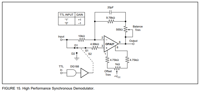
Through this circuit, we can get the amplitude of the testing signal but lost the phase information. Considering the internal resistance, inductance and capacitance of battery, if we keep the phase information it could be better to know the internal pure resistance of battery. Do you have any idea about this?
Hi Ruixin,
the phase information isn't lost. It can be derived from the ratio of the output signals of two synchronous demodulators
Kai
Hi Ruixin,
this might interest you:
https://www.tina.com/blog/synchronous-modulator-and-demodulator/
Burr-Brown The Instrumentation Amplifier Handbook-1.pdf
Kai
Hi Kai,
Appreciated it! I have several questions and hope you can answer.
1. Does the ratio of output signals you mentioned mean the testing signal multiply reference signal and its 90 degree phase shift one? The dual phase lock-in amplifier, right?
2. For internal resistance tester, there is a 1kHz excitation signal added to battery. And the measurement signal of battery is also 1kHz. We want the phase information of measurement signal compared with excitation signal. But can we make excitation signal as reference signal since they are same frequency?
Rayna
Rayna
It seems best that this post be taken offline. Please make a friend request to Kai if you have follow up questions for him and I will also reach out to you offline to provide any potential options from our comparator team.
Chuck