Other Parts Discussed in Thread: INA333,
Hello everybody, I have a big problem with my INA122P amplifier. I put force sensor (CZL204E) to determine the mass on it. However, the voltage was too low. So, I decided to use a wheatstone bridge to amplify this voltage. (the sensor is commonly describe as a variable resistance).
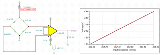
I use the circuit (in attached files) with a gain resistor (Rg) = 150 ohms so the gain must have been 1300 but actually the gain is only 150. I don't understand why , is my circuit false or did I do mistake in my solding ? Sorry for my english.

https://www.casimages.com/i/210503041747500210.png.html
https://www.active-robots.com/3137-button-load-cell-0-200kg-czl204e.html#specifiaction