A related question is a question created from another question. When the related question is created, it will be automatically linked to the original question.
If you have a related question, please click the "Ask a related question" button in the top right corner. The newly created question will be automatically linked to this question.
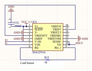
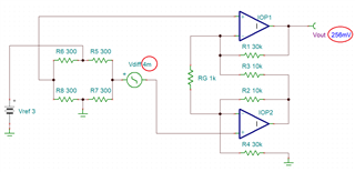
Our customer is having an issue with the INA125. Below are the details and the attached schematic. Appreciate your inputs on this.
They feed device with 3V They used an external 3v source to feed the load cell. They press the load cell and they can read a difference of 1-4 mv between s+ and s- with the multimeter. 10k resistor were used to generate an amplification of 10. The Aout pin of the device is always around 900mv and nothing changes even if they press the load cell.
They are using the same device in two different boards and they get the same result.
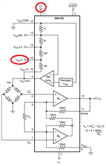
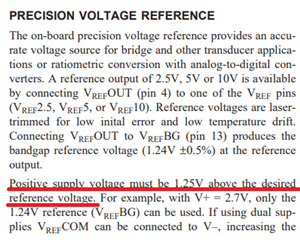
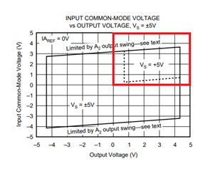
The issue is that by connecting pin 15 to pin 4 you attempt to use internal Vref_out of 5V BUT internal Ref_Amp (see below) cannot drive the output to 5V while using 3.3V supply voltage, V+.
If you absolutely need a Vref of 5V, you must increase the supply voltage above 6.25V - see below.
Customer is now feeding the load cell with an external 3v source and not with the reference voltage.
Finally he has now connected pin 4 with pin 13, but is not using this voltage, just the external 3v. Even with this configuration he can not see any change in the VAout when he use the load cell.
Also he has connected V- (pin3) to GND directly. Is that okay?
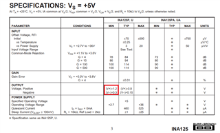
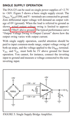
I believe the issue is caused by the violation of the INA125 output voltage range. On a single 3V supply, the linear output range is from 0.3V to 1.8V (see datasheet table below) but with the output referenced to ground your customer attempts to drive it too close to negative rail.
For 1mV-4mV differential input voltage, in Gain of 64, the output would have to swing between 64mV to 256mV, which is below the minimum specified of 300mV.
To solve the issue you may either:
1. Reference the output voltage above the ground by connect IAref (pin 5) to voltage of 250mV or higher
2. Use a negative supply (pin 3) of at least -250mV
3. Power negative supply (pin 3) with LM7705 (-230mV negative charge pump generator)
4. Increase the gain to at least 300 (RG=200phm) so for Vdiff=1mV Vout>300mV
Upon implementing the proposed solution, below are the follow-up inquiries from the customer in verbatim.
"1) I connected a resistor divider from vcc to pin 5 to get 300mV. When I read the value given by the divider I get correctly those 300mV, but when I connect the divider to the pin 5 I get 598mV
2) I increase the gain from 10 to 16 (5k resistor ).
3) now I am reading some changes in VAout but this: * When I don't do anything I read 600mv * When I use the load cell I read 1mv between s+ and s- and 602-604 mV in VAout..like a gain of 4...not 12
¿Why those 600mV? ¿Why this 598mV in pin 5? ¿Why that gain?"
what of the proposed changes did the customer carry out? Can the customer show an updated schematic?
It would be a good idea to take higher supply voltages and especially bipolar supply voltages (!) at the beginning and to reduce them to the intended values later. I say this, because sometimes the load cell show so high offset voltage that with small supply voltages or even single supply voltage (!) the output signal can disappear in the output saturation and no one might understand what's going on
So again, get the circuit running with recommended standard (bipolar!) supply voltages and - if everything is working fine - reduce the supply voltages to the wished level in a second step.
For the circuit to work properly, customer needs to implement only one of the recommendations above and NOT all of them:
1. Reference the output voltage above the ground by connect IAref (pin 5) to voltage of 250mV or higher
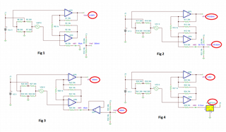
IAref must be a low impedance source and thus customer may NOT directly connect voltage from a resistive divider to pin 5 because as the current flows in or out of voltage divider this will cause error (see Fig 2 below) - thus, the 300mV output must be buffered before connecting it to pin 5 (see Fig 3). Alternatively, customer may use REF3312 (1.25V reference voltage) to drive pin 5 (see Fig 4).
4. Increase the gain to at least 300 (RG=200phm) so for Vdiff=1mV Vout>300mV
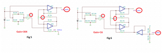
Increasing the gain to 16 for Vdiff=1mV results in the output of: Vout=Vref+1mV*16 =16mV (for Vref=0). This is way below the minimum of 300mV linear range of the INA125 output stage. Thus I recommended gain of 304 so the circuit works with pin 5 being grounded (see Fig 5).
However, if you drive IAref to 300mV you may use any gain you wish - just rememeber to use a buffer for 300mV voltage divider, or reference voltage like REF3312, to drive IAref pin 5 (see Fig 6).