This thread has been locked.

If you have a related question, please click the "Ask a related question" button in the top right corner. The newly created question will be automatically linked to this question.

LMH6629: LMH6629 used as TIA non-inverting Configuration and noticing a Noise Peak @1.73 GHz

Part Number: LMH6629
Other Parts Discussed in Thread: TINA-TI, THS4304

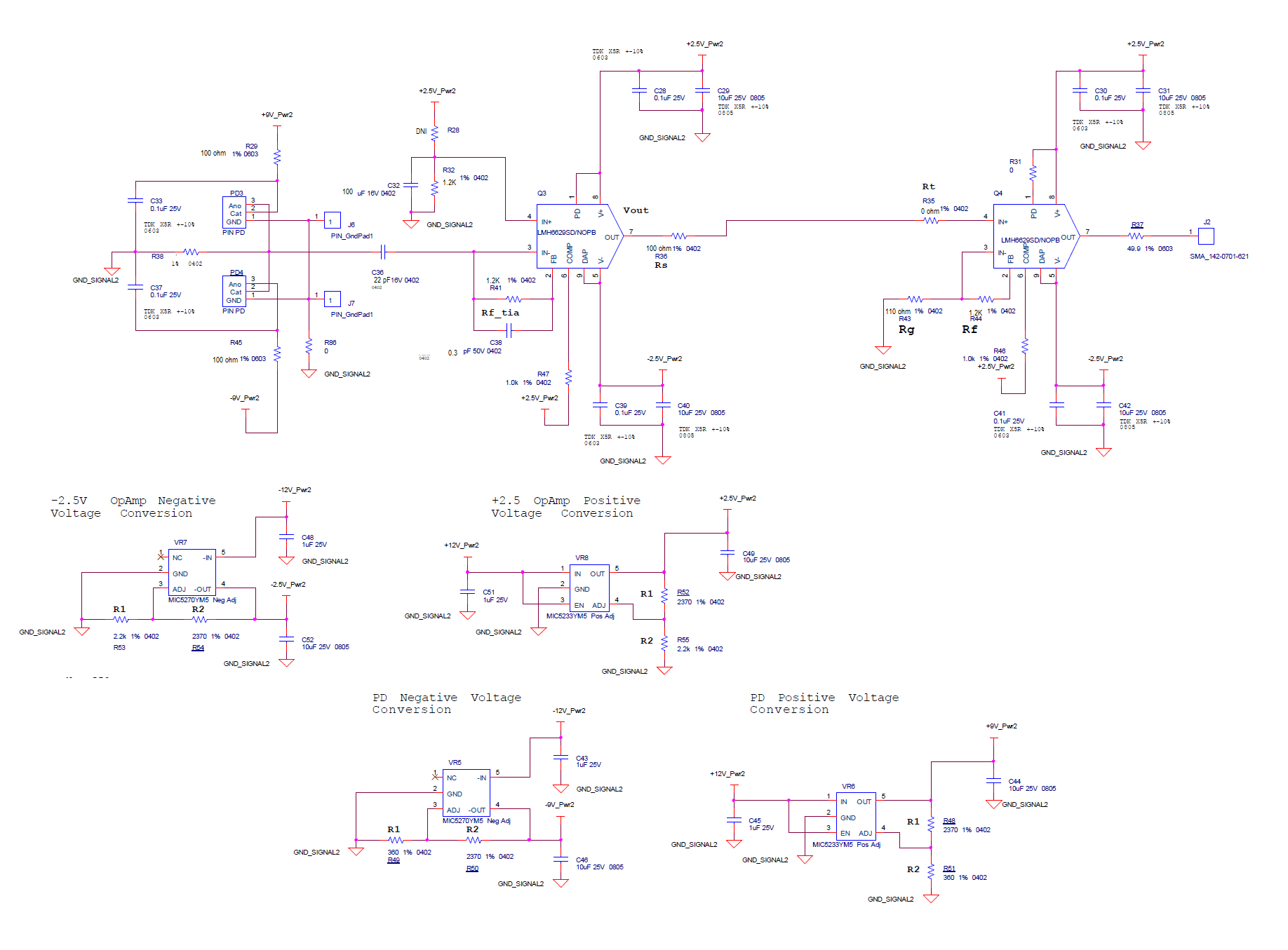
As shown in the following schematics, the LMH6629 has been configured/used as TIA (non-inverting configuration). We built several of them and we have been noticing a noise peak@1.73 GHz on few of them. What could cause this noise peak to occur at that frequency?

For more info:

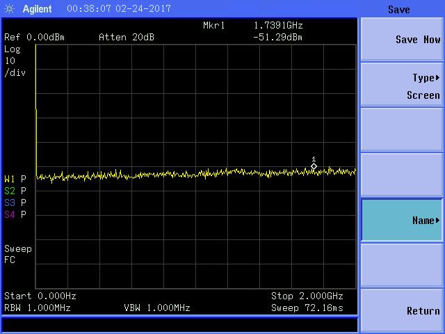
Attached schematics, spectrum analyzer screen capture, and actual PCB board snapshot.

Please let me know if you have any questions or concerns.

Thanks

Madhukiran Panabakam

NO Noise Peak Board: Spectrum Analyzer Screen Capture

Noise peak board: Spectrum analyzer screen capture

  • In all probability the amplifier doesn't have sufficient phase margin. This doesn't look like a typical TIA application..where is the actual input being applied to the circuit. Your schematic isn't coming through with good resolution. Can you please draw out your circuit (only the LMH6629 TIA part) in TINA-TI, detailing exactly how you are connecting the photodiode/SiPM to the LMH6629
  • Hi Samir,

    Thank you for the prompt response. I tried to create that circuit using TINA-TI but somehow LMH6629 TIA part is not in TINA with the same package. Anyway, the images which I attached are high resolution images. If you click on the schematics image it does show pretty good, and you can zoom-in if you want closer look of the part.

    I really appreciate your support as we are having this problem at customer site and we are on very tight schedule.

    Also, I forgot to mention that there was not optical input on the diodes when we see this noise.

    Thanks

    Madhu

  • Hi Madhu,

       There is only a single model for both packages. This is close enough for initial study. You can open up the model macro by double clicking on it and checking what all is simulated and what isn't.

    Attached is a TINA circuit. Can you please answer the questions in the red text within the schematic and also confirm I haven't made any other mistakes in my setup. Once you do that I can run some quick tests.

    Also, when you mentioned "no optical input", please confirm if the diodes are still present, but you are not stimulating them in any way??

    Looking at the PCB it looks like there is a bit of inductance between the photodiodes and the actual amplifier input. This can be detrimental to a high-speed amplifiers stability. Please try to minimize this as much as possible. Can you also zoom out a bit so I can see where the actual photodiodes are?

    -Samir

    LMH6629_Schem.TSC

  • LMH6629_Schem-edited.TSCHi Samir,

    I am no expert in this circuit but will try my best to answer your questions.

    Yes, you are right.. diodes are still present, but I am not stimulating them in any anyway.

    I added one comment on the top of C2 cap. Can you confirm that ?

    Please let me know if you have any questions or concerns.

    Best regards

    Madhu

  • Hi Madhu,
    C2 is a 300fF capacitor. Thanks for the other information - I will run some simulations and get back to you.
    -Samir
  • Hi Samir,

    Did you run some simulations ?

    Please let me know your findings.

    Best regards

    Madhu

  • Madhu,

      Attached simulation shows a phase margin of only 24 degrees implying possible oscillation. In addition to this the inductance from the photodiode leads could make things worse. For a start can you please reduce R38 to say 100 ohms and check if the oscillation goes away?

    -Samir

    LMH6629_LoopGain-Analysis.TSC

  • Hi Samir,

    We will try the recommended changes and will get back to you with the spectrum analyzer plots.

    Best Regards
    Madhu
  • Hi Samir,

    We did following modifications and tests:

    1. R38 (100 ohm) : Peak still exists

    2. R38 (Short) : Peak still exists

    3. R38 (10 K ohm): Peak still exists, but disappears when we close the lid of the box.

    4. R38 (1K ohm): Peak still exists

    5. Cleaned Solder blobs: Peak still exists

    Please let us know if we are missing anything in this.

    Best regards

    Madhu

  • Madhu,
    Couple of things to try -

    1. Remove the photodiodes on the board and retest the part. Bring R38 back to 100 ohms. The amplifier will be most stable in this configuration.

    2. After doing (1) above also experiment with the COMP pin. Bring that low and see if the problem persists.

    3. Uninstall R35 and see if that changes anything. Is there a way to add a load resistor to GND on the 1st amplifier?

    4. How do you know that the oscillations are from amplifier 1 or 2? Is there a way to remove amplifier 2 and measure the output of amplifier 1 directly?

    This is going to be a step-by-step debug process as we eliminate possible causes.

    -Samir
  • Hi Samir,

    As per your suggestion, we tried step 1 and here are the results of the test:

    NO-PhotoDiode; R38:1K

    Same with/without LID

    NO-PhotoDiode; R38: 100 ohm (Noise peak @1.5569GHz, -23dBm)


    With Lid


    Without Lid


    Now regarding the other experiments, I have few questions:

    2. COMP Pin: Do you want me to GND that pin or just keep reducing the voltage (+2.5V, +2.0V, +1.5V, +1.0V, +0.5V, 0.0V)

    3 and 4, I think we can do this.

    Please let us know your feedback for the plots we sent for experiment 1.

    Best Regards

    Madhu

  • Madhu,

    1. It is very odd that R38 = 1kOhm than 100 ohm seems to be more stable. I expected it to be the other way around. It almost sounds like something is coupling into the inputs directly and being amplified. Can you please change the resistor from 100ohm to 200ohm and see if the size of the peak is reduced.

    2. COMP pin can be directly set to 0V. It is not an analog input....it is digital, so either a HIGH or LOW.

    -Samir
  • Hi Samir,

    Here is the result for 200 ohm. I zoomed in (2/div instead of 10/div). Anyway I attached all three plots .

    200ohm- 10/div

    NO-PD-200OHm-WITHOUTLID

    No-PD-200OHM-zoomedin-WITH LID

  • Hi Samir,

    One more correction. It was my bad, by mistake I had C32 (C4 in your schematics) as 100uF, it was suppose to be 100pF.

    Do you see any difference with this change ?

    Thanks

    Madhu

  • Madhu,
    You can increase that C32 to 100nF for improved noise rejection. I don't think its the cause but its worth trying.

    Also, just to summarize, with the photodiode removed and :

    R38 = 100 ohm, peaking

    R38 = 200 ohm, no peaking

    R38 = 1 kohm, no peaking

    Is that an appropriate summary? If so then something is off, because as the gain increases stability improves. If it doesn't then the source of that peak may not be amplifier stability related.

    -Samir
  • Yes, you are summary is right and that is what plots look like. If you want I can double check that process.

    Thanks
    Madhu
  • Manu,
    At this point I am unsure what the issue is since the behavior is inconsistent with amplifier stability theory. You could purchase an EVM and experiment on that as well to see if you see the same effect.

    Also try my earlier suggestions:

    3. Uninstall R35 and see if that changes anything. Is there a way to add a load resistor to GND on the 1st amplifier?

    4. How do you know that the oscillations are from amplifier 1 or 2? Is there a way to remove amplifier 2 and measure the output of amplifier 1 directly?

    -Samir
  • Hi Samir,

    Thank you for your help with the oscillation at 1.73 GHz. There is another issue with this design that we would like your thoughts on...

    The LMH6629 datasheet says the overload recovery time is about 2 ns. Experiments seem to indicate that in our circuit, the overload recovery time is several hundred nanoseconds. Any ideas on why it is so long?!

    Thanks,

    Dan

  • Hi Dan,

    The LMH6629 datasheet says the overload recovery time of 2ns for input signal swing of 1Vpp.
    What is the input signal swing at the LMH6629 for your overload recovery application?

    Best Regards,
    Rohit
  • Hi Rohit,

    Thank you for your reply. I will gather the data and reply soon.

    In the meantime, I was able to track down the date codes for the chips under test. Is it possible there was an issue with them?

    Date code:1449

    Lot code:4499039EM4

    Thanks,

    Dan

  • Hi Rohit,

    I did some measurements. If you read the thread, you'll see our circuit has two LMH6629--one for trans-impedance and one for 10x gain. During the high intensity optical return (pulse about 300 ns long), the input swing to the first stage is about 0.2 Vpp. The input swing to the second stage is 4 Vpp. That is obviously higher than the 1 Vpp in the datasheet, but how does it de-rate to 4 Vpp?

    We do not care about the high intensity return and are effectively "blind" during that 300 ns pulse. However, I need to measure tens of nanoseconds later and thought the 2 ns in the datasheet would be fine.

    What do you think?

    Thanks,

    Dan

    PS: Any thoughts on the date code post?

  • Hi Dan,

    Unfortunately, there is no good way of de-rating a 1Vpp input overload specification to a 4Vpp input overload spec because the transistors are fairly non-linear at this point, and it is very tough to predict non-linearity unless you measure it on the bench. The 1Vpp input with a gain of 10 in itself is a stressed overload condition, and with 4Vpp input certainly the overload does not get better (rather gets more worse).

    One thing you can try is to reduce the input current signal to a level that gives 1Vpp at the 2nd stage LMH6629 input, and see if it recovers in ~ 2ns. If it does, then what you are seeing at 4Vpp is very likely real and is an overload characteristic of the LMH6629. If that is the case, then would it be possible to reduce gain of the 2nd stage amplifier? The LMH6629 is a decompensated amplifier, so I would not recommend using it below gain of +4V/V. You could also look at the THS4304 in a gain of +2V/V configuration which should have similar or better overdrive recovery than the LMH6629.

    I am sorry but I haven't had a chance to look at the date codes. I will check to see and get back.

    Best Regards,
    Rohit
  • Hi Rohit,

    Any luck with the date code? Anything unusual reported for that batch?

    Thanks,

    Dan

  • Hi Dan,

    Sorry for the delay in reply. I checked to see if the date and lot code you provided had an issue in the batch and it seems there was no issue with the batch.

    Best Regards,
    Rohit