This thread has been locked.

If you have a related question, please click the "Ask a related question" button in the top right corner. The newly created question will be automatically linked to this question.

OPA547: Non-Inverting amp output voltage swing versus power supply question

Part Number: OPA547
Other Parts Discussed in Thread: OPA548

Hello! 

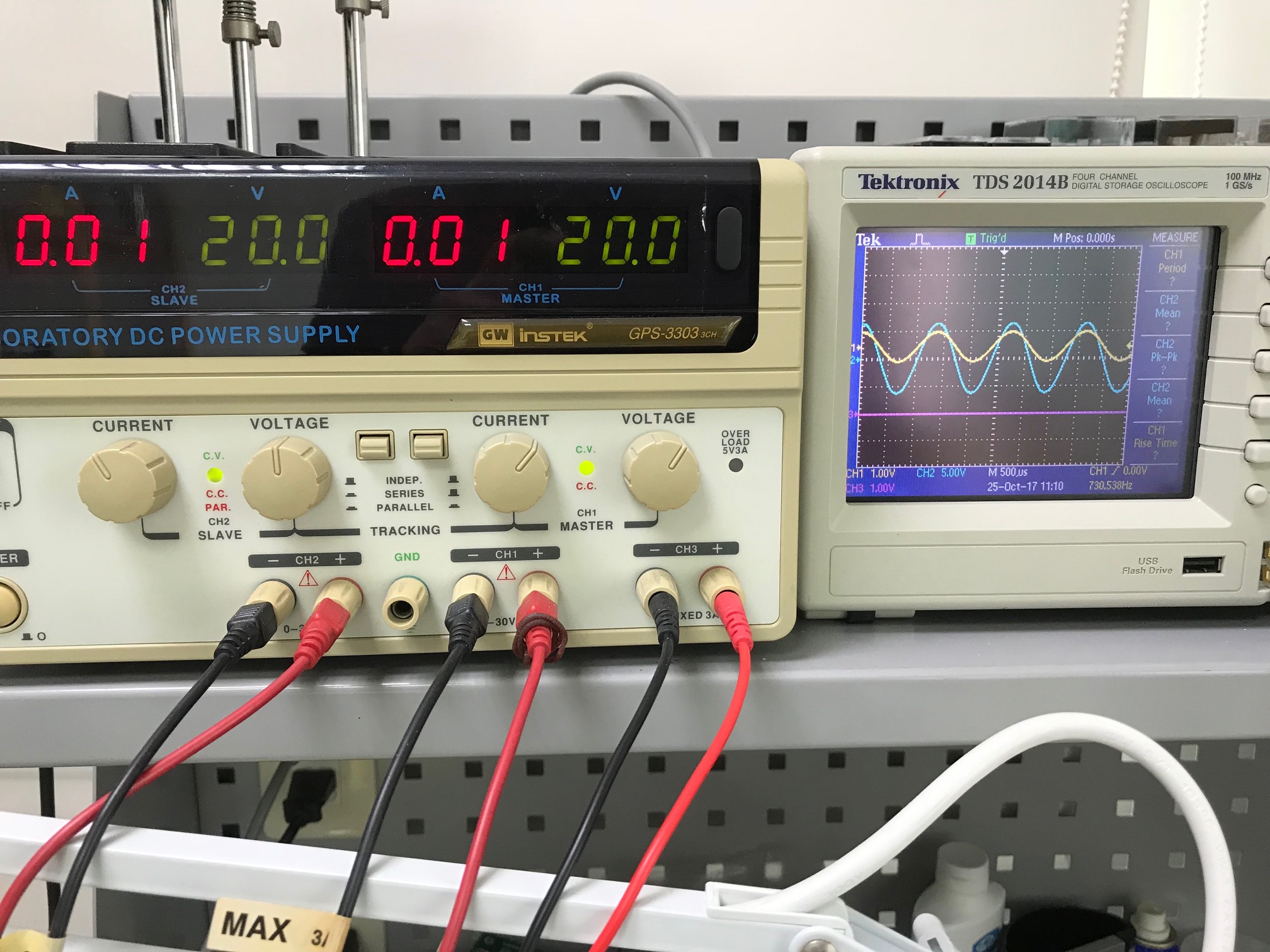
I am trying to built a voltage amp wiht +/- power supply(+/-15V). According to data sheet output voltage can swing up to V+ -1.92V, V- +1.3V, ideally if my feedback resistor setup gain is hight enough , I should be able to obtian a +/- 13Vpp output. But result is always limited to less than half of power supply rail.

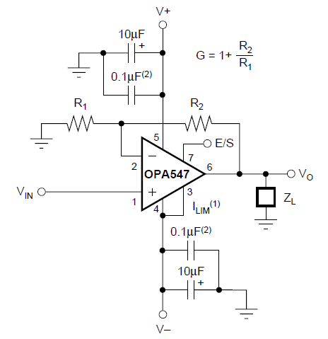
Why is this happening ? my set up is according to Figure 1. "Basic Circuit Connections" from OPA547 data sheet.

  • Hello Simon,

    You don't mention anything about your load resistance, or where you have the current limit set for the OPA547. If they are not correctly set the output will current limit and the swing will be reduced. Also, make sure you power supply isn't current limiting.

    Can you tell us your Vin signal level and frequency, what you have the current limit set to, and what the output load resistance is? Have you made sure you have followed all the thermal and heat sinking requirements?

    Seeing your exact OPA547 circuit schematic would be helpful to us.

    Regards, Thomas
    Precision Amplifiers Applications Engineering
  • Hello! Thomas,

    Thanks for your reply. See below my set up, V+,V- ~= +/-15VDC, Current is not limited on power supply neither on OPA(pin 3 ,Pin 4 shorted). R2=3.9K, R1 = 470, load = 5ohm. input signal = 1Vpp, output looks nice~ = 10Vpp. But when trying to increase R2, output is limited to second photo. Please give me your comment. Thanks very much!

    See photo 1 output is 

  • Hello Simon,

    Thank you for the additional information. If your circuit is being operating in the condition where the output voltage is 10 Vpp, then the peak voltage is 5 Vpk. A load of 5 Ohms will result in a peak current of 1 Amp. The OPA547 can provide a continuous output current of 500 mA providing the datasheet conditions are met, "With TC = 25°C the maximum output current of 500mA can be achieved under most conditions. Increasing the case temperature reduces the safe output current that can be tolerated without activating the thermal shutdown circuit of the OPA547." So under the right thermal conditions the peak output current may get up to 750 mA, but I wouldn't expect 1 Amp peak.

    You mention increasing the value of R2 which would raise the closed-loop gain. If the output could deliver even higher current, then the peak output voltage would increase accordingly. However, the OPA547 is almost certainly running out of drive capabililty and may even be going into thermal shutdown. Try increasing the load resistor value to something like 10 Ohms and see if the swing increases.

    If you really need 1 Amp output current, or more, try the OPA548.

    Regards, Thomas
    Precision Amplifiers Applications Engineering
  • Hi! Thomas,

    Thank for your reply. I tried increased the load but doesn't help on increasing output voltage, it seemed setup did not go into current limited that's limiting output voltage. But, if I increase power supply voltage , the output voltage does increase, see attached photo. That is something I do not understand datasheet showing +/- output voltage is V+ -2.2V , V- +1.9V, in my test set up I can only see output voltage swing range always limited to half of power supply rail voltage. You can also see current from the power supply shows only 0.1A current flow over +/- 20V.

    My target design is to hav an amplifier with +/-15V supply , to be able to amplify a 1~2V signal to 26Vpp. I though it should be achievable after seeing data sheet of OPA547, the output signal performance of OPA547 is great, but now I am stucked because of the output swing limitation..... Please help me on this. Thanks!

  • Hi Simon,

    I am not finding anything obvious with your OPA547 datasheet Figure 1 circuit that would explain the output issue; so, it looks like we need to look for a not-so-obvious cause.

    One thought I have had is with regard to the OPA547 package tab and what you have connected it to. The datasheet figure shown below indicates that the tab is internally connected to V-. The tab must be connected to a heat sink or heat sinking PC board surface to remove the internally generated heat, but that heat sink  potential must be at either V-, or floated, and not connected to any other dc potential. The tab isn't intended to be connected to ground in a dual supply configuration and doing so would create a problem.

    Another possibility is the OPA547 you are evaluating is damaged. Although the OPA547 product is fully tested before shipment there is the possibility it could have been damaged after being removed from its ESD safe packaging. Have you tried a different OPA547 in your circuit?

    Regards, Thomas

    Precision Amplifiers Applications Engineering