Because of the holidays, TI E2E™ design support forum responses will be delayed from Dec. 25 through Jan. 2. Thank you for your patience.

This thread has been locked.

If you have a related question, please click the "Ask a related question" button in the top right corner. The newly created question will be automatically linked to this question.

LM675: Distortion and instability taking place

Part Number: LM675
Other Parts Discussed in Thread: OPA564, OPA544

Attached is a drawing of a section of the circuit which currently uses the LM675T. The op amp is attached to heat sink and dead bugged into the proper nodes on a vector board. Vsig is a sinusoid which will go as high as +/-0.5V and up to 1Mhz. If Voffset = 0, the crossover “hiccup” occurs, the hiccup is about 2 us. As the frequency is increased, it becomes more noticeable and the sinusoid becomes “less pure”. Frequency does not seem to alter the 2us crossover time. If DC offset (positive or negative) is added enough to where the AC signal doesn’t cross 0, the sinusoid looks great, no visible difference between the signal and the LM685T output. If increased up to 1.5-2A with a DC offset so there is no 0 crossing, and up to 200kHz and there isn’t any noticeable distortion in the output. Looking for an op amp, which has a minimal crossover time so up to 20Khz (more comfortable with 50-200kHZ max) can be achieved, < 1% purity error in the sin wave output.


Interesting instability, if a DMM is wired in series with the 1 ohm resistor load to measure the current, the LM675T seems to go nuts and gives a 2A DC output and gradually decreases, it also shows large amounts of noise added to the Vsig +in line. This behavior is the same whether the cap and resistor connector -in or +in are present or not. This behavior did not happen when OPA544 was used. This seems to be repeatable. The OPA544 does have about a 10us crossover hiccup though.

  • Hi Claire,

    the LM675 needs the Zobel-Network 1R/220n at its output to work stable. Have a look into the datasheet.

    Kai
  • Hi Claire,

    Repeating your text, and adding comments:

    Attached is a drawing of a section of the circuit which currently uses the LM675T. The op amp is attached to heat sink and dead bugged into the proper nodes on a vector board. Vsig is a sinusoid which will go as high as +/-0.5V and up to 1Mhz.

    The LM675 is internally compensated for closed-loop gains of 10 V/V and higher. It can be set for closed-loop gains of less than 10 V/V,  but the amplifier must be carefully compensated. Datasheet Fig. 12 shows a non-inverting unity-gain (+1 V/V) buffer and that circuit and associated equations should be used. The Zobel RC network that Kai mentions should included as well.

    Note that with the Fig. 12 compensation that the LM675 circuit has a new gain-bandwidth value of 50 kHz. That is an outcome of re-compensating the amplifier. You are applying an input signal with a frequency up to 1 MHz, which is certainly too high for a re-compensated LM675.

    If Voffset = 0, the crossover “hiccup” occurs, the hiccup is about 2 us. As the frequency is increased, it becomes more noticeable and the sinusoid becomes “less pure”. Frequency does not seem to alter the 2us crossover time. If DC offset (positive or negative) is added enough to where the AC signal doesn’t cross 0, the sinusoid looks great, no visible difference between the signal and the LM685T output.

    The LM675 output stage normally operates class AB and crossover distortion does occur. At low frequencies where the open-loop gain (Aol) is very high, and consequently the corresponding loop-gain is high, the class AB crossover distortion is much reduced. As the frequency is increased and Aol and the loop-gain fall off the cross-over distortion increases and becomes more evident when viewed with a DSO.

    Adding the offset moves the output away from 0 V, and one or the other output transistor sinks or sources the output load current. The other transistor goes along for the ride. When output transistor is providing the output it is operating class A and the crossover distortion is eliminated.

    If increased up to 1.5-2A with a DC offset so there is no 0 crossing, and up to 200kHz and there isn’t any noticeable distortion in the output. Looking for an op amp, which has a minimal crossover time so up to 20Khz (more comfortable with 50-200kHZ max) can be achieved, < 1% purity error in the sin wave output.

    The highest gain-bandwidth (GBW) power op amp that we can offer is the OPA564. Its typical GBW is rated at 17 MHz, the slew rate is 40 V/us and it is unity-gain stable. Since its GBW is about 3x that of the LM675 its Aol will be comparatively higher, out to a higher frequency resulting in improved crossover distortion. Do note that the OPA564 power supply range and maximum output current are different from the LM675 so make sure they meet your needs. You can find the OPA564 datasheet here:

    Interesting instability, if a DMM is wired in series with the 1 ohm resistor load to measure the current, the LM675T seems to go nuts and gives a 2A DC output and gradually decreases, it also shows large amounts of noise added to the Vsig +in line. This behavior is the same whether the cap and resistor connector -in or +in are present or not. This behavior did not happen when OPA544 was used. This seems to be repeatable. The OPA544 does have about a 10us crossover hiccup though.
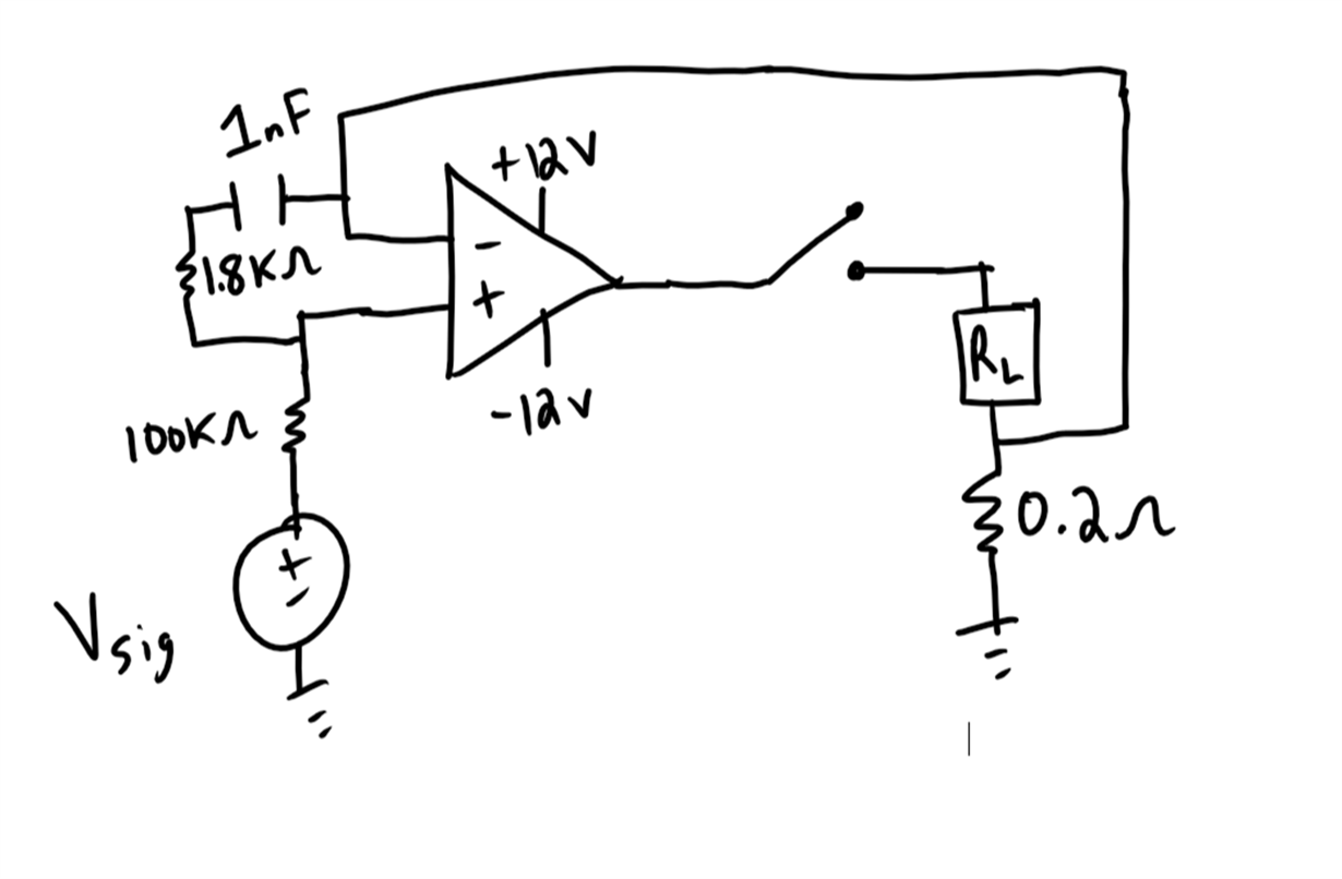
    It sounds like the amplifier isn't properly compensated in this configuration.

    Regards, Thomas

    Precision Amplifiers Applications Engineering

  • Claire

    We haven't heard back from you so we assume this answered your questions. If you need additional help just post another reply below.

    Thanks
    Dennis