This thread has been locked.

If you have a related question, please click the "Ask a related question" button in the top right corner. The newly created question will be automatically linked to this question.

AFE031: signal distortion

Part Number: AFE031
Other Parts Discussed in Thread: LAUNCHXL-F28379D, C2000WARE,

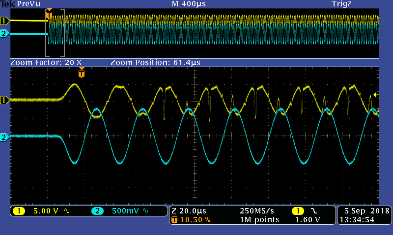
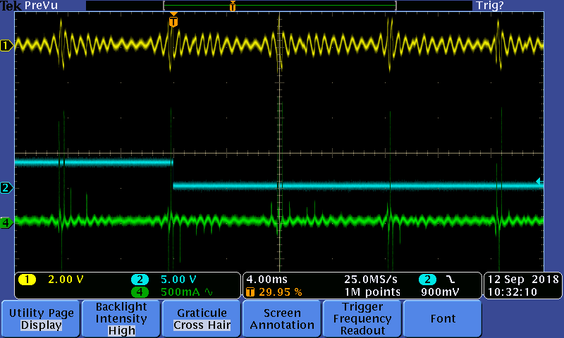
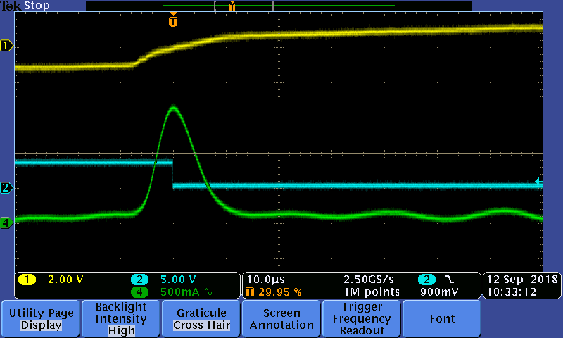
We're unable to get an OFDM PLC application to communicate successfully. Our 64 carriers are in the 25k to 65kHz i.e. CENELEC A band. Investigating I used a function generator to generate discrete sine waves in lieu of the OFDM signal. I connected the output of the function generator to the AFE031 'TX_PGA_IN' pin. Function generator output was 3.1Vpp 1.65Vos. AFE031 'TXPGA' gain was set to 0.5. Building 120VAC was connected to secondary of coupling transformer after series LC. Output was monitored AFE031 'PA_OUT'. I expected in band sine waves, amplified by 3.25, to be seen at the output.  This was the case for ~25k-30kHz. However at 35k to 40kHz the output was severely distorted. I've attached a screen shot of the distorted waveform and AFE031 schematic. Does the distortion make sense? Does the design make sense?

thanks

Mark

-0167 P1 sheet 4.pdf

  • Hi Mark,

    We are looking over your AF031 schematic and the DSO image you provided. Can you provide more details about the R1 and R2 waveforms captured by the DSO (frequency, etc.)? You mention the output was monitored at the PA_OUT. There are two waveforms shown. Is this simply PA_Out at two different times, or two points in the circuit? What peak-to-peak output voltage are you attempting to achieve?

    Regards, Thomas
    Precision Amplifiers Applications Engineering
  • For the purposes of this discussion you can disregard the R2 waveform. Per PRIME the requirement is > 1Vrms with a 2 ohm load. However the distorted waveform seen at PA_OUT is when the output is connected to 120VAC. Why is this sine wave distorted? The frequency is in the 25k-65kHz band we've designed for. The signal looks fine with no load.

    thanks
    Mark

    this is urgent!!

  • Hi Mark,

    We have had discussions on this end regarding your AFE031 application and what you are seeing. The waveforms you show in the DSO images shows the output folding back on the positive and negative peaks. This could indicate that the AFE031 is going into thermal shutdown as the peak is approached, staying shutdown on the peak, and then the output recovering after momentarily cooling.

    The AFE031 datasheet describes the shutdown behavior on Pg. 40, "Thermal Overload - The AFE031 contains internal protection circuitry that automatically disables the PA output stage if the junction temperature exceeds +150°C. If a fault condition occurs that causes a thermal overload, and if the T_FLAG_EN bit (location 5 in the Control2 Register) is enabled, the T_FLAG bit (location 5 in the RESET Register) is set to a '1'. This configuration results in an interrupt signal at the INT pin."

    It is unclear to me from your schematic if the function is being utilized and monitored. If you are able to monitor the thermal shutdown function, then that would provide a definite verification if this is occurring, or not.

    The reason that this could occur has to do with the impedance of the 120 VAC line load at the lower vs. higher CENELEC frequencies in the band. If the load at the higher CENELEC frequencies results in more output current being demanded from the AFE031, then its power dissipation increases causing the transmitter output transistors to heat more so than at lower current levels. The reason the output looks good with no load is because there is very little heat being generated by the output transistors. You might experiment with an increasingly heavier resistive load and see if at some point the distortion begins to occur.

    Thermal shutdown is the result of the PC board not being able to dissipate the heat. The solution in that case is to redesign the board for increased heat dissipation.

    Regards, Thomas
    Precision Amplifiers Applications Engineering
  • Thomas,

    This morning I verified your logic. An over current condition was flagged immediately when a 12ms burst of 40kHz was started. I later saw that this flag was generated shortly after the PA was enabled in the absence of any burst. The aforementioned was with a 120VAC load.

    I'm seeing the same thing when there is no load, 120VAC removed.

    I'm also seeing that after I cycle AFE031 power, INT starts out HI but immediately goes LO if all I do is enable the flags
    RESET Register 0x09 reads 0xC0.

    In order for these flags to operate properly does the PA block and/or PA output need to be enabled?

    Is there a certain sequence to accessing the AFE031 registers that needs to be followed?

    Till now our sequence has been:
    1) write 0x7 to 0x01 to enable PA, TX and RX blocks
    2) write 0x11 to 0x02 to set RX_PGA1 gain to 0.5 and TX_PGA gain to 0.5
    3) write 0x0E to 0x03 to enable REF1, REF2 and PA output stage

    Thanks - You've been a great help
    Mark
  • Hi Mark,

    We are going to have to look into your register sequences so I don't have an answer about that just yet.

    Would it be possible for you to take a look at the AFE031 PA_IN pin with a DSO and see if there is any drop out on the peaks as is observed at PA_OUT? I suspect that it is not happening at that point in the circuit, but confirmation of it helps us focus on a possible PA issue.

    Also, if you short the series LC filter after the 1:1 transformer does the waveform peak behavior change anywhere in the CENELEC A band?

    Regards, Thomas

    Precision Amplifiers Applications Engineering

  • Thomas

    CH1 is PA_OUT, CH2 is TX_F_OUT

    Both screen shots are the same with but 1st one CH2 is 500mV/div while 2nd one CH2 is 200mV/div

    LC filter attenuates 120VAC so that AFE031 PA_OUT only see's µVAC, so can't short it

    Mark

  • I forgot to mention that I changed the PA_ISET resistor from 10k to 7.8k to see what a higher current setting would do. No noticeable difference.
  • Hi Mark,

    Thanks for capturing the images. That tells us that we need to focus on the AFE031 PA circuit. Also, it is good information about decreasing the PA_ISET resistor to increase the current limit value didn't have an effect. If current limiting were the issue the peaks on the waveform would plateau and not fold back. Thermal limiting shuts down the output stage and causes the output waveform to collapse. 

    An idea you might try is to reduce the temperature of the AFE031 while the output is exhibiting the fold-back behavior. If you have some freeze spray available it can be used to temporarily cool the device. The AFE031 thermal pad is on the underside of the device and the thermally conductive PC board plane is usually accessible from the bottom of the board. If you can spray the PC board underside area where the AFE031 is located with the freeze spray that should prove an effective way to cool down the device. If you observe upon spraying the coolant that the voltage peaks appear as they do at the lower CENELEC frequencies, then that tells us we are on the right trail.

    Regarding the register settings, one of my applications colleagues has been looking into your questions. He provided me the following:

    Extracted this from the datasheet..

    "The last paragraph on page 40 emphasizes correct programming of Control2 Register (Address 5), which is missing from Mark’s sequence, along with programming of Control1 Register (Address 4) and Reset Register (Address 9).  I also confirmed that our C2000/LaunchPad AFE031 examples do program both Control Registers as well as the Reset Register. Most likely, his register programming is not the root cause of the problem."

    Hopefully, this is of help.

    Regards, Thomas

    Precision Amplifiers Applications Engineering

  • Thomas,

    We've never seen the thermal overload flag. To the touch I've never felt the chip heat up unless I'm driving 120VAC continuously with sine wave in CENELEC A band. That is why I only drive the chip for ~12ms with an external function generator. The waveforms I sent you are the result of a a single 12ms burst of 40kHz. Doing the burst once a second the duty cycle is 1.2% and the chip never gets hot to the touch. Intuitively I would expect the chip to get excessively hot to go into to generate a thermal overload flag. Is there something wrong with my reasoning?

    Your application engineer collegue's response with regards to programming register sequence is confusing. Can you give us the exact programming sequence from the C2000/LaunchPad example?

    thanks
    Mark
  • Hi Mark,

    Even though your test is a burst condition, that may be long enough for the junctions in the AFE031 PA to heat to a temperature where thermal shutdown is being activated. The thermal impedance is complex from the transistor junction to the outside world. The are several series time constants and the one associated with the transistor junction and surrounding silicon can be such that the junction heats very rapidly if the power to be dissipated is high. If you can try the cooling experiment it would either confirm, or dispel a thermal issue.

    My colleague is not here right now so I can't give you an immediate answer regarding your request about the exact programming sequence from the C2000/Launchpad - just yet. When I see him, I'll let him know of your request.

    Regards, Thomas

    Precision Amplifiers Applications Engineering

  • Thomas,

    As soon as I can find some cold spray I'll do as you ask. Repeating I've never seen the thermal flag set.

    I've noticed that a over current flag occurs shortly (a few seconds) after the PA is enabled WITHOUT any signal being transmitted.

    thanks Mark
  • Hi Mark,

    Do you have access to a wide bandwidth clamp-on current probe for a DSO? It would be very helpful if you could capture both the output voltage and output current images at the PA_Out point in the circuit on the same screen.  DSO information captured at a frequency where the output waveform is normal and not folding back , and another at a frequency where the output waveform is folding back could prove very useful in developing an understanding of the cause of the distortion.

    Here is the information my colleague provided:

    The C2000/LaunchPad example programs require Code Composer Studio, which can be downloaded here:

     http://www.ti.com/tool/CCSTUDIO

     C2000Ware examples demonstrate FSK Transmit and Receive applications that target the C2000/LaunchPad (LAUNCHXL-F28379D) and AFE031 BoosterPack (BOOSTXL-AFE031). C2000Ware can be downloaded here:

     http://www.ti.com/tool/C2000WARE

     The companion TI Reference Design application note is here:

     http://www.ti.com/tool/TIDA-060001

     After downloading/installing Code Composer Studio (CCS) and C2000Ware, an example project can be imported into CCS to view the AFE031 programming sequence. Using default installation paths, the typical location of the AFE031 DAC mode example is:

     C:\ti\c2000\C2000Ware_1_00_05_00\device_support\f2837xd\examples\cpu1\boostxl_afe031_f28379d_dacmode

     After importing the example project, the main function and AFE031 programming sequence can be viewed in the boostxl_afe031_f28379d_dacmode_main.c and afe031_config.c source files, respectively.

    NOTE: One should be able to simply download C200Ware to view the AFE031 DAC mode example source code in their preferred  program editor (i.e.  CCS and LaunchPad/BoosterPack hardware is not needed to simply browse source code).

    Regards, Thomas

    Precision Amplifiers Applications Engineering

  • Hi Thomas,

    We're noticing that the status of the interrupt/thermal flags in the RESET register are valid anytime it is read. The hardware interrupts associated with these flags are only active if Control2 Register bits 5 and 6 are SET. If this is correct the Control2 Register description for these bits is misleading because it should sate that 'interrupts are disabled/enabled' instead of 'flag bits in RESET register disabled/enabled'. Do you concur?

    The AFE031 configuration examples your colleague has sent us never enable the over current interrupt only the thermal limit interrupt.

    Over current interrupts happen immediately when they are enabled if PA_OUT is NOT enabled. As such PA_OUT must be enabled before we enable over current interrupts. Can you explain this? Why can't the interrupts be enabled before PA_OUT is enabled?

    What does the AFE031 do when it detects an over current condition besides generate the flag? Page 40 of the data sheet states that it goes into 'current limiting mode' but what exactly is this mode and how does it affect the output and for how long? When does it come out of this mode? How can we tell if its no longer current limiting. What does it do if the over current condition is just momentary?

    I'm working on getting the PA_OUT current monitor probe in place like you asked.

    Thanks
    Mark
  • Hi Mark,

    We are going to have to review the register sequences before we will be able to provide concordance with your explanation.

    Regarding your other questions:

    What does the AFE031 do when it detects an over current condition besides generate the flag?

    When the PA goes into current limiting the output current cannot exceed the programmed limit which is set by the equation in the datasheet:

    ILIM = 20 kΩ • [1.2 V/(RSET + 5 kΩ)] A

    Page 40 of the data sheet states that it goes into 'current limiting mode' but what exactly is this mode and how does it affect the output and for how long?

    Once the current limit is established by the RSET value the output will provide any current level up to the ILIM level. The op amp operates in a normal linear manner. If the load attempts to draw a current level higher than ILIM the output will be limited to the ILIM value. This results in clipping the output waveform. This behavior is continuous and operates in that mode until the output current demanded is below ILIM.

    When does it come out of this mode? 

    It drops out of the current limiting mode when the output current required by the load is less than ILIM

    How can we tell if its no longer current limiting.

    The output current should be less than the ILIM value. Any clipping of the output waveform should cease.

    What does it do if the over current condition is just momentary?

    Normal, non-ILIM operation should resume.

    I'm working on getting the PA_OUT current monitor probe in place like you asked.

    I appreciate that effort. It should provide valuable information.

    Regards, Thomas

    Precision Amplifiers Applications Engineering 

  • Thomas,

    Here are screen shots of the over current detection. Note that these occurred with the PA output enabled but no signal driving the input. Maybe I should put a pull down resistor at the PA_IN pin to insure the input is 0V in this condition.

    With your description of what current limiting does I don't see how current limiting could produce the screen shots I sent you at the beginning of this thread. Do you concur?

    What is the status of AFE031 register programming sequence?

    thanks

    Mark

  • Hi Mark,

    You mention the screenshots of the over-current detection. The Current Overload section on Pg. 40 of the datasheet discusses the IFLAG bit, location 6, in the RESET register. Is that where the images are being captured? Can you explain each of the three traces?

    With your description of what current limiting does I don't see how current limiting could produce the screen shots I sent you at the beginning of this thread. Do you concur?

    The original DSO images that you provided show that fold back characteristic on the output signal peaks. A current limited condition would flattop at the current limit ILIM setting established by RSET value. The two different conditions thermal shutdown and current limit, have a different effect on the output waveform when present. I concur.

    What is the status of AFE031 register programming sequence?

    My colleague is looking into your question. I will ask him when he will be able to provide an answer.

    Regards, Thomas

    Precision Amplifiers Applications Engineering

  • Thomas,

    The 2nd screen shot is just zoomed in around the time of over current interrupt shown in the 1st screen shot. The RESET register is 0x04 after this interrupt.

    1) the 1st trace is PA_OUT. PA_OUT is enabled and AC coupled. There is no signal driving PA_IN and PA_IN is internally biased to 6VDC.
    2) the 2nd trace is the /INT
    3) the 3rd trace is a current clamp I have on PA_OUT. The 2nd screen shot shows a current spike of ~1.65A

    With regards 1) I'm not sure why there is any signal present. I would think the signal would be ~0VDC with maybe a bit (100mV) of noise. It looks to be the source of the over current interrupt. Where is it coming from? Perhaps the AC/DC converter being used on the board is back feeding this into the PA_OUT. The AC/DC supply is a board mount Mean Well MPM-10-12. Your thoughts?

    thanks
    Mark
  • Hi Mark,

    With regard to AFE031 register programming:

    We're noticing that the status of the interrupt/thermal flags in the RESET register are valid anytime it is read. The hardware interrupts associated with these flags are only active if Control2 Register bits 5 and 6 are SET. If this is correct the Control2 Register description for these bits is misleading because it should sate that 'interrupts are disabled/enabled' instead of 'flag bits in RESET register disabled/enabled'. Do you concur?

    Yes, along with the I_FLAG and T_FLAG bits in the RESET register, the Control2 register enables/disables the INT pin output.

    The AFE031 configuration examples your colleague has sent us never enable the over current interrupt only the thermal limit interrupt.

    True, the C200Ware example only enables the thermal overload flag/interrupt.

    Over current interrupts happen immediately when they are enabled if PA_OUT is NOT enabled. As such PA_OUT must be enabled before we enable over current interrupts. Can you explain this? Why can't the interrupts be enabled before PA_OUT is enabled?

    This observation requires further investigation.

    What does the AFE031 do when it detects an over current condition besides generate the flag? Page 40 of the data sheet states that it goes into 'current limiting mode' but what exactly is this mode and how does it affect the output and for how long? When does it come out of this mode? How can we tell if its no longer current limiting. What does it do if the over current condition is just momentary?

    Output current is limited, or clamped, regardless of whether or not the register flag and interrupt pin are enabled. According to the datasheet (page 40), the RESET register can be polled to determine if current limiting has occurred. Evidently, if the I_FLAG has been set, it will have to be cleared prior to subsequent reads to determine if the device is actively limiting current or not.

    Regards, Neil
    Precision Amplifiers Applications Engineering

    Furthermore, the device limits, or clamps, its output current regardless of whether or not the register flag and interrupt pin are enabled. When load decreases, the output current will no longer be clamped. According to the datasheet (page 40), the RESET register can be polled to determine if current limiting has occurred. Evidently, if the I_FLAG has been set, it will have to be cleared before subsequent reads to determine if the device is actively limiting current or not.

  • thanks

    Requested AFE031 programming sequence some time ago. What is the status of that request.

    Mark
  • Hi Mark,

    Aside from your observation on the INT output and I_FLAG being asserted immediately if interrupts are enabled prior to PA output, I believe your register programming concerns have been addressed in previous posts. Please let me know if you have additional register programming questions.

    Since my previous post, I have confirmed your observation/device behavior, i.e. the INT output and I_FLAG is asserted immediately if interrupts are enabled prior to PA output. To avoid this initial (anomalous) current limit event, simply enable interrupts as the last step in the register programming sequence. Then, subsequent (actual) current limit and thermal shutdown events can be detected via the INT pin and/or the RESET register flags. Again, the RESET register flags (I_FLAG and T_FLAG) should be polled and cleared to detect device transitions into and out of current limiting and/or thermal shutdown.

    Having said that, can you tell us (via observation of the INT output and polling/clearing the RESET register) if the device is transitioning into and out of current limiting and/or thermal shutdown while outputting the carrier signal?

    Regards, Neil
    Precision Amplifiers Applications Engineering
  • Mark

    We haven't heard back from you so we assume this answered your questions. If not just post another reply below.

    Thanks
    Dennis