This thread has been locked.

If you have a related question, please click the "Ask a related question" button in the top right corner. The newly created question will be automatically linked to this question.

XTR117: 4-20mA 2-wire with 0-10V 3-option

Part Number: XTR117
Other Parts Discussed in Thread: XTR115, XTR110, XTR111

Hi,

i'm looking for a way to use XTR117 with 4-20mA 2-wire and 0-10V 3-wire jumper selectable.

There are many of sensors working like this in the market and i need to follow this model. My first design was like this:

The problem is that the Iret current seems to be the minimum current i can see in the OUT, so i can't see values near zero on 0-10V.

Is there a way to use multiple jumpers to force component's current to make another path, or any other XTR component that i can use for both 4-20mA 2-wire and 0-10V 3-wire?

Thanks,

Rodrigo

  • Hi Rodrigo,

    I assume the IRET and DAC "GND" connection is allowed to float with respect to the loop ground 4-20mA loop Ground, Is this correct?

    The XTR117 is a 4-20mA 2-wire transmitter.  As you have mentioned, one challenge of the 2-wire transmitter is that the minimum current output is the current consumption of the sensor circuitry + XTR117 and therefore the 2-wire sensor transmitters consumption must be less than 4mA.  Please check the "minimum-scale Current" section on p6 of the XTR115 datasheet (very similar device).  There are ways to increase the current consumption above 4mA on the post below using a DC-to-DC converter.

    2-Wire 4-20mA – Increasing Sensor Power:
    https://e2e.ti.com/blogs_/b/precisionhub/archive/2015/04/14/2-wire-4-20ma-sensor-transmitters-background-and-common-issues-part-6

    However, I don't know of a simple way the XTR117 can be configured as a 0-10V input, 0-20mA 3-wire transmitter with jumpers.  Examples of 3-wire transmitter devices supporting 0-10V input, 0-20mA outputs are the XTR110 and XTR111.  

    Below is a presentation contrasting the 2-wired vs 3-wire transmitters that you may find helpful.

    Many Thanks,

    Kind Regards,

    Luis Chioye

    5850.4-20mA_Basics.pdf

  • Hi Luis,

    thanks for the reply.

    So, there's no easy way to do this, i see two possibilities.

    Redesign all circuit with non-integrated solution.

    Try to keep my consumption below 10% of the full range (as this circuit would work with a humidity sensor, it's very commom to use only 10-90% ranges),

    In this case i want my maximum output current to go as high as it can get, if i could modify the circuit to work with 40mA or at least 30mA i think i can manage to get to that 10% full range consumption.The datasheet says i can extend the current connecting a resistor from pin 3 to pin 5, how this work exactly? What resistor value should i use? In this case i can normally use the DAC/InputResistor adjust or it would add a fixed current output?

    -I already use a charge pump regulator 5-3.3V.

    Thanks,

    Rodrigo

  • Hi Rodrigo,

    I apologize for the delay in the response.

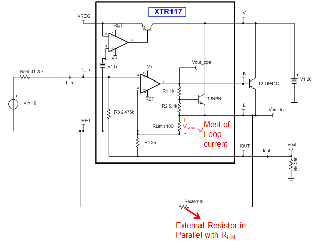
    The internal RLIM resistor provides roughly a current limit of 32mA;  this current limit is not precise and is only intended to protect the device and keep the current below 45mA to avoid damage.  Most of the Loop current flows to RLimit (about 99% of the current) and therefore, the RLIM resistor produces an internal voltage drop between IRET and the emitter of the internal and external NPN transistor.  When the loop current is around ~32mA, the internal circuitry starts to run out of headroom and the output current is limited.

    The value of the internal RLIM resistor is approximately ~100ohms.  When connecting an external resistor between pin3 and pin5, you are effectively placing a resistor in parallel with RLIM reducing its value, and therefore increasing the current limit.   Unfortunately, I don't have an accurate simulation model for the current limit circuit, so I would need to get a hold of the eval board and perform some measurements.

    Placing an external resistor between pin 3 and pin 5 (changing RLIM) does not change the current gain, the output current equation remains Io= Iin*100.  Please note, the specified linear output range for the XTR117 is in the range of 0.25mA to 25mA.  At currents above 25mA the device will not meet the accuracy specs; and currents can not exceed 45mA to prevent damage.

    Many Thanks,

    Kind Regards,

    Luis