This thread has been locked.
If you have a related question, please click the "Ask a related question" button in the top right corner. The newly created question will be automatically linked to this question.
Hi all,
I'm using a TLV9064 quad op-amp in a cascaded active bandpass filter configuration. I fine-tuned my design using simulations and all is working fine now. But despite the 10MHz GBW of this op-amp the center frequency of my band-pass filter is still slightly dependent on variations in GBW.
The datasheet only mentions a typical value for GBW. Is there any information available about the variation in GBW? Does it also change with temperature?
Thanks.
Paul
--
Hi Kai,
Thanks for the quick reply.
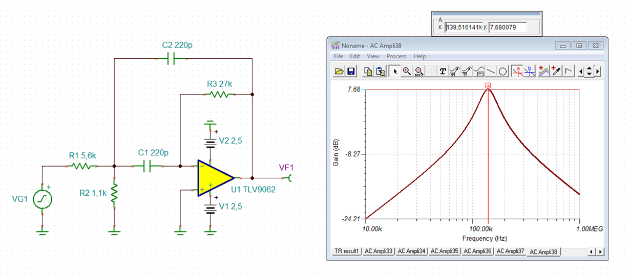
My filter consists of four identical cascaded sections like below:
The center frequency is supposed to be 137kHz which it is if GBW is 10MHz. When I change the GBW in the simulation to 12MHz the center frequency goes up to approx. 139kHz. My prototype also produces a peak at 139kHz which leads me to believe that the actual GBW of my op-amp is closer to 12MHz.
Regards,
Paul
--
Hi Paul,
Thanks for the reply.
Is that + or - 30% or the total span?
Paul
--
Hi Paul,
the ideal center frequency of your bandpass filter should be 148kHz and not 137kHz. This shift is already a consequence of the finite bandwidth of TLV9064. Another issue is that the cap values of your bandpass filter are rather small and that the input capacitance of TLV9064 can already play a role.
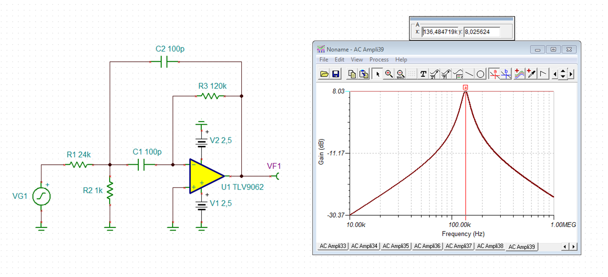
I would give this circuit a try:
It provides nearly the same gain and the same center frequency but a Q of only Q = 2.7.
This is the performance of your original bandpass filter:
Kai
Hi Kai,
I now have 4 identical sections giving me a total Q of about 15.
Would that be achievable with a state variable filter with only 3 opamps?
I' m not familiar with this topology but I'm open to sugestions.
Regards,
Paul
Hi Paul,
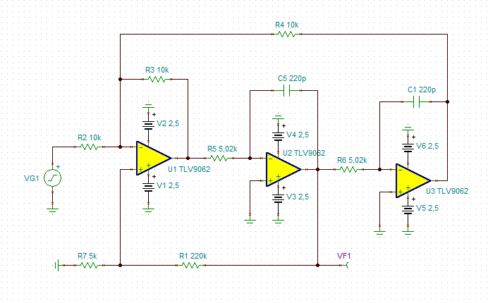
such a state variable filter could look like that:
Unfortunately, the simulation of this circuit doesn't work very well. The gain is much higher than theory predicts. So, I don't want show any results of the simulation. Don't know why...
The schematic might nevertheless be helpful?
Kai
Hi Kai,
I did some playing around with this topology and I managed to get it working in the simulation. The nice thing about it is that you can change Q without affecting the center frequency and vice versa.
And the GBW sensitivity of Fc is indeed much less then in my original filter topology, just like you mentioned.
But what I also found is that instead of Fc being dependent on GBW, now Q varies with GBW. That leads to the gain of the filter at the center frequency being variable which is another problem.
Another difference is that the roll-off on both sides of Fc is basically 1st order 20dB/decade where in my cascaded filter it is fourth order 80dB/decade. So in the vicinity of Fc the filter can be made quite steep by increasing Q but at the far ends of the frequency range the attenuation is limited.
I'm not sure which way to proceed yet ,but this was a very educational exercise anyway.
Thanks,
Paul
--
Hi Paul,
your observations make absolutely sense to me.
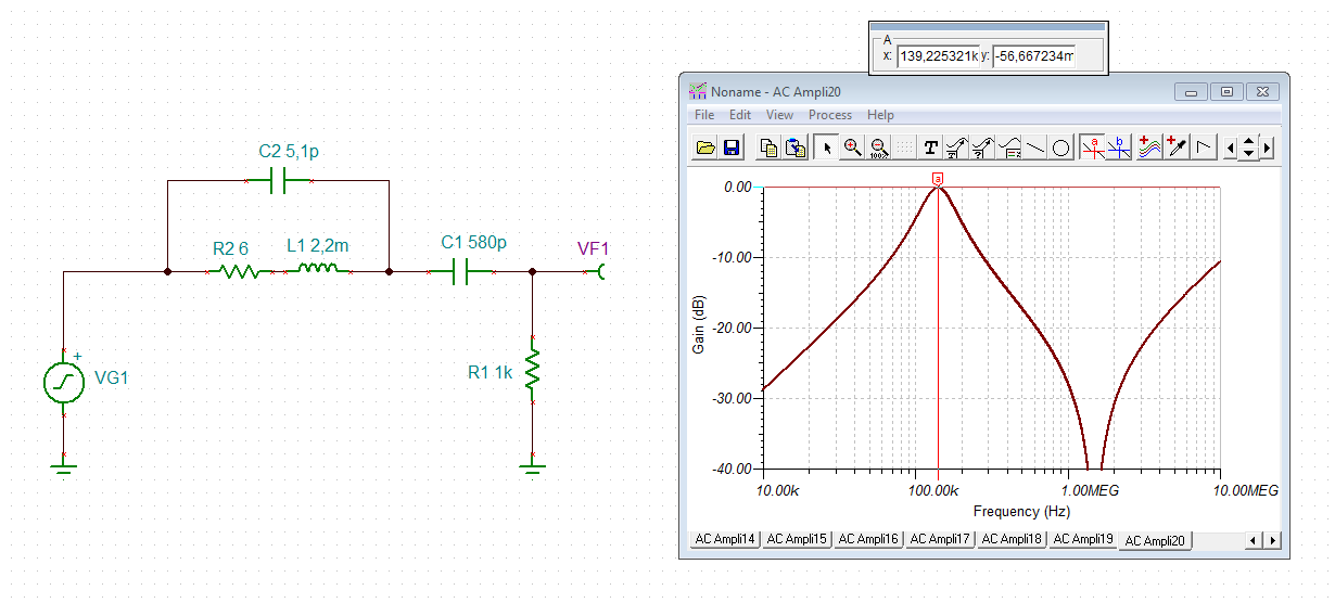
Don't beat me, but would an additional passive RLC-bandpass help?
R2 and C2 simulate the parasitics of B82144B choke.
Kai
Hi Kai,
Sorry for not replying earlier.
I had considered using a passive RLC filter earlier in the design process, but the need for a relatively large value inductor made this too expensive. I also experimented with smaller valued inductors but then the capacitors (which then become larger and need to be NP0 for accuracy) became too costly.
I think I have found a solution now where I can tune the center frequency of the active filter in order to adjust for differences in GBW.
So far that seems to work.
Regards,
Paul
--